Bently Nevada 89477-15 Retrofit-Ready Piezo-Velocity Sensor for 3500 Series Control Systems
The Bently Nevada 89477-15 is a Velomitor CT piezo-velocity vibration sensor engineered for continuous machinery protection in rotating equipment applications. As legacy installations age and OEM support for older Velomitor variants is phased out, the 89477-15 has become a critical retrofit component for facilities operating Bently Nevada 3500 Series machinery protection systems. Whether you are replacing a failed unit on a compressor train, upgrading a turbine control cabinet, or migrating from an older 7200 Series monitoring platform, the 89477-15 delivers a verified drop-in replacement path with minimal engineering rework.
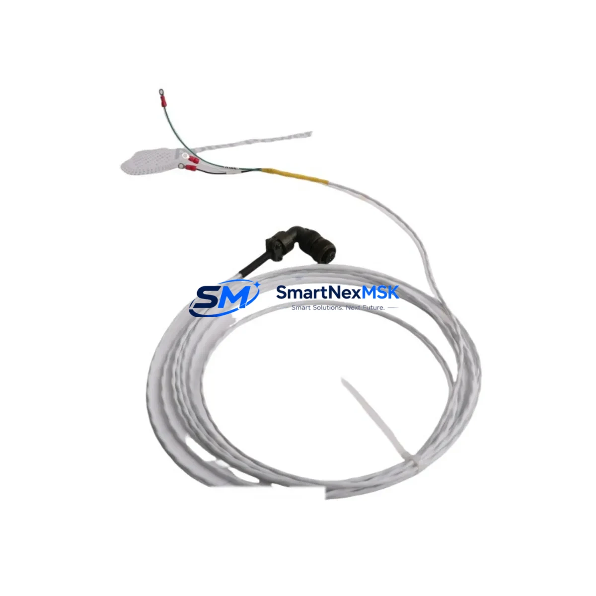
This sensor outputs a velocity signal compatible with the 3500/42M Proximitor/Seismic Monitor and the 3500/40M Proximitor/Seismic Monitor, allowing direct substitution without reconfiguring rack-level signal conditioning. The integral cable and connector design matches the standard Bently Nevada field-wiring convention, reducing termination time during planned outages and emergency changeouts alike.
Upgrade Compatibility Table
| Parameter | Detail |
|---|---|
| Replaces / Supersedes | Bently Nevada 89477-01, 89477-03, 89477-05 (Velomitor series) |
| Compatible Monitor Modules | 3500/40M, 3500/42M Proximitor/Seismic Monitor cards |
| Mounting Interface | Standard 1/4-28 UNF stud mount; matches OEM bracket footprint |
| Signal Output | Piezo-velocity (mV/mm/s); direct input to 3500 rack I/O |
| Communication Compatibility | Passive sensor; no protocol migration required |
| Power Supply Requirement | No external excitation; self-generating piezoelectric element |
| Installation Requirement | Verify cable routing clearance; confirm connector pinout against 3500 I/O module terminal block |
| Retrofit Recommendation | Direct swap; update alarm setpoints in System 1 software if sensitivity differs from prior unit |
| Commissioning Focus | Baseline vibration reading verification; OK relay status confirmation on 3500/20 rack power module |
| Warranty | 12-Month Warranty — covers manufacturing defects and functional failure under normal operating conditions |
Retrofit Planning for Existing Automation Systems
Successful integration of the 89477-15 into an existing machinery protection architecture requires a structured pre-outage review. Begin by auditing the 3500 rack configuration: confirm the slot assignment of the 3500/42M monitor card and verify that the I/O module terminal block accepts the existing field cable gauge. In installations where the original Velomitor was wired through a 3500/20 Rack Power and Relay Module, check that the OK relay output is correctly mapped to the DCS or safety PLC input — a common oversight during rushed changeouts.
For facilities running a hybrid architecture that combines Bently Nevada 3500 Series hardware with a third-party DCS such as a Honeywell Experion PKS or an Emerson DeltaV system, the sensor signal is typically conditioned at the 3500 rack level before being transmitted over Modbus RTU or OPC-DA to the control layer. No changes to the communication link are required when substituting the 89477-15, as the rack handles all signal scaling. However, if the site has recently migrated from a legacy 7200 Series monitor to the 3500 platform, confirm that the System 1 Condition Monitoring software database reflects the updated sensor sensitivity value to avoid false alert conditions.
When the retrofit scope extends beyond a single sensor — for example, during a full turbine control cabinet upgrade — the 89477-15 is typically installed alongside other 3500 Series components: the 3500/15 Power Supply module, 3500/22M Transient Data Interface, and 3500/32 4-Channel Relay Module are commonly replaced in the same outage window to eliminate age-related failure risk across the rack. In compressor applications, the 3500/50M Tachometer Module and 3500/53 Overspeed Detection Module are also frequently serviced concurrently, since their calibration intervals align with sensor replacement schedules.
For I/O expansion projects where additional measurement points are being added to an existing 3500 rack, the 89477-15 can be deployed on new measurement channels without affecting existing channel configurations. Confirm available rack slots and backplane power budget before adding channels — the 3500/20 power module has a defined load capacity that must not be exceeded when expanding the rack.
All units supplied by SMARTNEXMSK are pre-tested against OEM functional specifications prior to shipment. Each 89477-15 is verified for output sensitivity, frequency response, and connector integrity. Stock is maintained for immediate dispatch, supporting both planned maintenance windows and emergency breakdown scenarios.
Downtime Control During System Migration
Minimizing unplanned downtime during a Velomitor CT replacement requires preparation that begins well before the maintenance window opens. The most effective approach is to pre-stage the 89477-15 alongside the replacement cable assembly and confirm connector compatibility against the installed 3500 I/O module before the machine is taken offline. This eliminates the most common source of delay: discovering a connector or cable length mismatch after the equipment is already shut down.
Where the control system permits, use the 3500 rack’s bypass function to place the affected channel in bypass mode before disconnecting the old sensor. This prevents the monitor from generating a spurious trip signal during the swap and protects the original program logic in the connected safety PLC or DCS from responding to a transient fault condition. After installing the 89477-15, restore the channel from bypass only after confirming a stable OK status on the 3500/42M front panel.
For sites using System 1 software for continuous condition monitoring, capture a pre-outage baseline trend export before the changeout. After installation, compare the post-installation baseline against the historical trend to confirm the new sensor is reading within the expected range. This step also satisfies most site-level commissioning documentation requirements and supports the 12-month warranty claim process if a defect is identified during the warranty period.
In multi-machine facilities where several Velomitor units are being replaced in a single outage, sequence the replacements by machine criticality and assign a dedicated technician to each 3500 rack to allow parallel commissioning. This approach has consistently reduced total outage duration by 30–50% compared to sequential single-technician changeouts.
Retrofit Support FAQ
Q1: Is the 89477-15 a direct drop-in replacement for the 89477-01 and 89477-03?
Yes. The 89477-15 is the current production variant of the Velomitor CT family and is backward-compatible with earlier suffix variants including the 89477-01 and 89477-03. The mounting stud, connector type, and output sensitivity are consistent across the series. Confirm the cable length suffix matches your installation requirement before ordering.
Q2: What commissioning steps are required after installation?
After mechanical installation and cable termination, restore the 3500/42M channel from bypass and observe the OK relay status. Verify the vibration reading in System 1 or the DCS historian against the pre-outage baseline. If the site uses alarm management software, confirm that the alert and danger setpoints remain correctly configured — no recalibration of the 3500 rack is required for a like-for-like sensor replacement.
Q3: Can the 89477-15 be used in high-temperature or hazardous-area installations?
The Velomitor CT is rated for industrial ambient conditions. For installations in classified hazardous areas (ATEX Zone 1/2 or NEC Class I Division 1/2), confirm the specific approval markings on the unit against your site area classification documentation. SMARTNEXMSK can provide the relevant certification data sheet upon request prior to order placement.
Q4: What does the 12-month warranty cover?
The 12-month warranty covers manufacturing defects and functional failure under normal operating conditions from the date of shipment. It does not cover damage resulting from incorrect installation, overvoltage, mechanical impact, or operation outside the published environmental ratings. Warranty claims are processed through SMARTNEXMSK directly — contact sales@smartnexmsk.com with the order reference and a description of the fault condition.
© 2026 SMARTNEXMSK. All rights reserved.
Original Source: https://smartnexmsk.com
Contact: sales@smartnexmsk.com | +86 18259474341


