Bently Nevada 89477-34 Retrofit-Ready Velomitor for 3500 Series Control Systems
The Bently Nevada 89477-34 Velomitor Piezo-Velocity Sensor is a precision vibration measurement device engineered for seamless integration into existing 3500 Series machinery protection systems. As legacy installations age and original OEM spares become increasingly scarce, the 89477-34 serves as the definitive retrofit-ready replacement for discontinued Velomitor variants, enabling plant engineers to restore full vibration monitoring capability without redesigning the control architecture or replacing the entire monitoring rack.
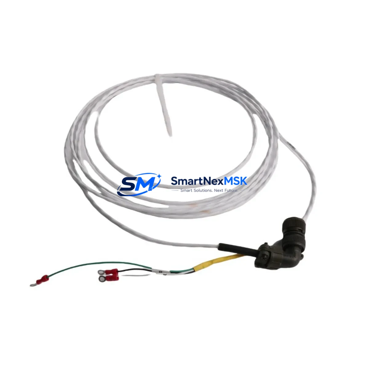
Designed for continuous operation in demanding industrial environments, the 89477-34 delivers broadband velocity output compatible with the Bently Nevada 3500/42M Proximitor/Seismic Monitor and the 3500/40M Proximitor Monitor. Its integrated signal conditioning eliminates the need for external amplifiers, and its rugged stainless-steel housing withstands high-temperature, high-vibration plant conditions typical of rotating machinery applications including turbines, compressors, pumps, and gearboxes.
For facilities managing aging DCS or PLC-based control platforms, the 89477-34 integrates directly into existing 4–20 mA or voltage-output signal chains without requiring firmware changes to the host controller. Engineers migrating from older Bently Nevada 7200 Series or 3300 Series monitoring frameworks will find the 89477-34 compatible with standard terminal block wiring conventions, reducing retrofit labor and minimizing the risk of signal chain errors during cutover.
Upgrade Compatibility Table
| Parameter | Detail |
|---|---|
| SKU / Part Number | 89477-34 |
| Brand | Bently Nevada |
| Compatible Monitor | 3500/42M, 3500/40M, 3500 Series Rack |
| Replaces / Supersedes | Discontinued Velomitor variants; 7200 Series seismic sensors (with adapter) |
| Output Signal | Piezo-velocity (integrated), compatible with standard BN signal conditioners |
| Mounting Interface | Standard Velomitor thread mount; no bracket modification required |
| Wiring Compatibility | Matches existing 3500 Series terminal block pinout; no rewiring required in most installations |
| Communication Protocol | Analog (4–20 mA / voltage); compatible with Modbus RTU via 3500 rack gateway |
| Backplane / Rack Interface | 3500 Series I/O rack; no backplane modification required |
| Module Address | Configured via 3500 Rack Configuration Software (RCS); no hardware DIP switch changes |
| HMI Compatibility | System 1 Evolution, Orbit software; no screen rebuild required for standard tag mapping |
| Installation Requirement | Torque to OEM spec; verify cable shield continuity post-installation |
| Commissioning | Zero-speed check, full-speed vibration baseline, alarm setpoint verification |
| Warranty | 12 Months from date of shipment |
Retrofit Planning for Existing Automation Systems
Successful retrofit of the 89477-34 into an operating plant begins with a thorough pre-outage audit. Engineers should document the existing sensor cable routing, confirm the cable type (typically Bently Nevada 330130 or equivalent low-noise coaxial), and verify that the 3500 Series rack power supply — commonly the 3500/15 Power Supply module — can sustain the additional sensor load without exceeding its rated output current. In multi-rack configurations, the 3500/20 Rack Interface Module should be checked for firmware revision compatibility with the replacement sensor’s signal profile.
Terminal block wiring should be mapped against the original as-built drawings before disconnection. The 89477-34 uses a standard two-wire connection to the 3500/42M input card; polarity and shield grounding must be verified to prevent common-mode noise from corrupting vibration readings. Where the original installation used the Bently Nevada 3500/92 Communication Gateway for Modbus or PROFIBUS integration, no gateway reconfiguration is typically required — the sensor replacement is transparent to the communication layer.
For plants running System 1 Evolution or the legacy Orbit software suite, HMI tag mapping remains unchanged provided the replacement sensor is assigned the same rack slot and channel address. The 3500 Rack Configuration Software (RCS) should be used to verify channel configuration, alarm setpoints, and full-scale range before returning the machine to service. Where I/O expansion is planned as part of the broader upgrade, the 3500/61 TDIX Termination Block and 3500/50 Tachometer Input Module are commonly added in the same outage window to avoid repeat shutdowns.
Plants upgrading from older 7200 Series or 3300 Series monitoring frameworks may require a Velomitor signal conditioner adapter to match the legacy cable impedance. In these cases, the 3300/16 Dual Velocity Monitor or the 3300/55 Dual Velocity Monitor (where still in service) should be decommissioned and replaced with the appropriate 3500 Series input card to complete the migration cleanly. Programming cables such as the Bently Nevada 3500/94 Serial Interface Module are useful for offline configuration verification before the new sensor is energized.
Downtime Control During System Migration
Minimizing unplanned downtime during a Velomitor replacement requires a structured hot-swap protocol. Where the process permits, the 89477-34 should be pre-configured and bench-tested against a known-good 3500 Series rack before the scheduled outage window. This includes verifying the sensor’s open-circuit voltage, confirming cable continuity, and running a simulated vibration input through the signal chain to validate alarm response in the 3500/42M monitor card.
During the physical swap, the original program logic in the host PLC or DCS — whether running on a Rockwell ControlLogix, Siemens S7-300, or ABB AC800M platform — should not be modified. The 89477-34’s analog output is fully compatible with existing AI (Analog Input) module configurations, so no I/O mapping changes are required in the controller program. This preserves the original ladder logic or function block diagram intact, protecting years of tuning and interlock logic from inadvertent modification.
Post-installation, a controlled run-up sequence should be performed: start the machine at minimum speed, confirm vibration readings are within expected baseline range on the System 1 or Orbit HMI, then step up to operating speed while monitoring for alarm trips. If the 3500 rack is configured with a 3500/22M Transient Data Interface, transient capture should be enabled during the first run-up to establish a new vibration signature baseline for future predictive maintenance reference. Total planned downtime for a single-sensor swap in a well-prepared outage is typically two to four hours, including cable verification and post-commissioning sign-off.
Retrofit Support FAQ
Q1: Is the 89477-34 a direct drop-in replacement for my existing Velomitor without rewiring?
In the vast majority of 3500 Series installations, yes. The 89477-34 uses the same thread mount, cable connector, and two-wire terminal block interface as the original Velomitor. Verify your existing cable part number against the 89477-34 datasheet before installation. If your installation uses a non-standard cable assembly, a Bently Nevada-compatible extension cable may be required.
Q2: Will I need to reconfigure my 3500 rack or update firmware after installing the 89477-34?
No firmware update is required for standard 3500/42M or 3500/40M monitor cards. Use the 3500 Rack Configuration Software (RCS) to confirm that channel sensitivity, full-scale range, and alarm setpoints match your process requirements. No rack-level reconfiguration is needed if the sensor is installed in the same slot and channel as the original unit.
Q3: How do I verify wiring integrity and sensor function before restarting the machine?
Perform an open-circuit voltage check at the terminal block with the sensor powered but the machine at rest. Confirm the bias voltage is within the 89477-34’s specified range. Then apply a calibrated vibration source or use the 3500 rack’s built-in self-test function to verify end-to-end signal integrity from sensor to HMI display. Document the zero-speed baseline reading before machine start-up.
Q4: What warranty coverage is provided, and what does it include?
All 89477-34 units supplied by SMARTNEXMSK carry a 12-month warranty from the date of shipment. Coverage includes manufacturing defects, signal output failure, and connector integrity. Each unit undergoes pre-shipment functional testing. Warranty claims are processed via sales@smartnexmsk.com with proof of purchase and a fault description. Physically damaged units resulting from incorrect installation are excluded from warranty coverage.
© 2026 SMARTNEXMSK. All rights reserved.
Original Source: https://smartnexmsk.com
Contact: sales@smartnexmsk.com | +86 18259474341


