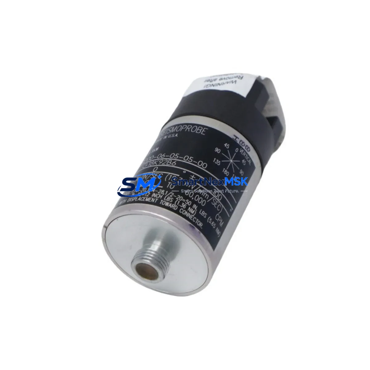
Bently Nevada 9200-06-05-03-00 Retrofit-Ready Eddy Current Transducer for 9200 Series Control Systems
The Bently Nevada 9200-06-05-03-00 is a precision eddy current transducer engineered for direct retrofit into legacy 9200 Series vibration monitoring installations. As original 9200 Series components approach end-of-life or become increasingly difficult to source, this unit provides a verified drop-in replacement path that preserves existing wiring, conduit runs, and signal conditioning infrastructure. Whether you are managing a planned upgrade cycle or responding to an unplanned failure on a critical rotating machine, the 9200-06-05-03-00 is designed to restore full monitoring capability with minimal downtime and without requiring reprogramming of the host monitoring system.
This transducer operates on the established eddy current proximity sensing principle, delivering a linear DC voltage output proportional to the gap between the probe tip and the observed shaft or target surface. The output is fully compatible with the signal input requirements of Bently Nevada 3500 Series monitoring racks, making it a practical bridge component when facilities are migrating from standalone 9200 Series field instruments toward the more integrated 3500 Machinery Protection System platform. Engineers undertaking this migration path should verify that the existing Proximitor® sensor — typically a 3300 XL 8mm or 3300 XL 11mm series — remains within calibration tolerance, as the transducer and proximitor must be used as a matched system to maintain measurement accuracy.
Before installation, technicians should confirm the available power supply capacity within the control cabinet. The 9200-06-05-03-00 draws from the same -24 VDC rail commonly shared with other field instruments, and adding or replacing transducers on an aging power distribution module — such as a legacy 9200 Power Supply or a 3500/15 Power Supply module — requires a load audit to prevent rail sag that could affect adjacent channels. Terminal wiring follows the standard three-wire coaxial arrangement: center conductor (signal), shield (return), and outer jacket (ground). Technicians replacing an in-service unit should document the existing terminal assignments before disconnection, particularly on multi-channel junction boxes where wire labeling may have degraded over years of service.
Backplane and rack compatibility is a key consideration for facilities running mixed-generation hardware. The 9200-06-05-03-00 is designed for use with 9200 Series extension cables and is compatible with standard Bently Nevada coaxial extension cable assemblies in 5-metre and 9-metre configurations. When the transducer is installed in a rack alongside a 3500/40M Proximitor I/O Module or a 3500/42M Proximitor Seismic Monitor, the channel configuration in System 1 software or the 3500 Rack Configuration Utility must reflect the correct transducer type, gap voltage, and scale factor to ensure that alarm setpoints and danger thresholds are correctly applied.
Upgrade Compatibility Table
| Parameter | Detail |
|---|---|
| SKU / Part Number | 9200-06-05-03-00 |
| Brand | Bently Nevada |
| Series Compatibility | 9200 Series; compatible signal interface with 3500 Series MPS |
| Sensing Principle | Eddy Current (Non-contact proximity) |
| Output Signal | DC voltage, linear with gap distance |
| Power Supply Requirement | -24 VDC (verify rail capacity before installation) |
| Wiring Interface | 3-wire coaxial; compatible with standard 9200 Series terminal blocks |
| Extension Cable Compatibility | Standard Bently Nevada coaxial extension cables (5 m / 9 m) |
| Rack / Backplane Interface | 9200 Series rack; signal compatible with 3500/40M and 3500/42M I/O modules |
| Communication Protocol | Analog (4–20 mA / DC voltage); no fieldbus protocol required |
| Replacement Recommendation | Direct drop-in for 9200-06-05-03-00; verify proximitor pairing |
| Commissioning Note | Recalibrate gap voltage and scale factor in 3500 Rack Configuration Utility after installation |
| Warranty | 12 Months from date of shipment |
| Country of Origin | United States |
Retrofit Planning for Existing Automation Systems
A successful retrofit of the 9200-06-05-03-00 into an operating plant environment requires a structured pre-outage planning process. Begin by auditing the full sensor chain: the transducer itself, the matched Proximitor® sensor (confirm whether the installed unit is a 3300 XL 8mm Proximitor or a 3300 XL 11mm Proximitor, as these are not interchangeable with the transducer without recalibration), the coaxial extension cable, and the termination at the monitoring rack input card. Any degradation in the cable jacket or connector body — common in installations exceeding ten years — should be addressed during the same outage window to avoid a repeat intervention.
Within the control cabinet, verify that the 9200 Power Supply or the replacement 3500/15 Power Supply module can sustain the additional load if multiple transducers are being replaced simultaneously. It is common in older installations to find that the power supply module has been operating near its rated output for years, and adding even a single additional transducer channel without a load audit can introduce instability. If the facility is also upgrading the monitoring rack to a 3500 Series chassis, the 3500/01 Rack Interface Module and the 3500/20 Rack Configuration Module should be configured before field wiring is connected, reducing the risk of false alarms triggering protective shutdown during commissioning.
For facilities that operate HMI systems — whether a legacy Wonderware InTouch panel or a more recent FactoryTalk View SE station — the channel tag assignments and engineering unit scaling must be updated to reflect the new transducer’s output characteristics. If the HMI historian is logging gap voltage trends, a gap in the trend data during the replacement window should be documented and annotated to prevent misinterpretation during future reliability reviews. Communication links between the 3500 rack and the plant DCS — typically via a 3500/92 Communication Gateway Module using Modbus RTU or Modbus TCP — should be verified after commissioning to confirm that all channel status words and measured value registers are updating correctly.
Downtime Control During System Migration
Minimizing unplanned downtime during a transducer replacement or system migration is the primary operational concern for maintenance teams. The 9200-06-05-03-00 is stocked for immediate shipment, which eliminates the lead-time risk that is common with OEM-sourced replacement parts for legacy 9200 Series components. For planned outages, we recommend pre-staging the replacement transducer, extension cable, and any required terminal block adapters at least 48 hours before the maintenance window begins.
Before disconnecting the in-service transducer, record the current gap voltage reading from the monitoring rack display or from the System 1 software trend screen. This baseline value serves as the acceptance criterion during recommissioning: after the new 9200-06-05-03-00 is installed and the gap is set to the manufacturer’s recommended nominal gap distance, the output voltage should fall within the linear range specified on the transducer calibration certificate. If the reading deviates beyond the acceptable band, recheck the proximitor pairing and the extension cable continuity before concluding that the transducer itself is at fault.
Original PLC program logic — whether resident in a legacy Allen-Bradley PLC-5, a ControlLogix L7x controller, or a Siemens S7-300 safety system — does not require modification when replacing a like-for-like transducer within the same signal chain. The monitoring rack handles all signal conditioning and alarm logic internally, and the PLC receives only the processed status and measured value outputs via the communication gateway. This architecture means that the control program remains intact and the machine can be returned to service as soon as the transducer gap is verified and the monitoring rack channel is re-enabled, keeping total intervention time within a typical four-hour maintenance window.
Retrofit Support FAQ
Q: Is the 9200-06-05-03-00 a direct replacement for all 9200 Series eddy current transducers?
A: The 9200-06-05-03-00 is a direct replacement for units sharing the same part number. For adjacent 9200 Series variants with different probe diameter or range specifications, confirm the full part number before ordering. Our technical team can assist with cross-reference verification.
Q: Do I need to recalibrate the system after installing the replacement transducer?
A: Yes. After installation, set the physical gap to the nominal value specified in the Bently Nevada installation drawing, then verify the output voltage against the transducer’s calibration certificate. Update the scale factor and gap voltage parameters in the 3500 Rack Configuration Utility if migrating to a 3500 Series rack. Document the as-found and as-left gap readings for your maintenance records.
Q: What wiring changes are required when retrofitting from a 9200 Series rack to a 3500 Series rack?
A: The field wiring from the transducer and extension cable to the junction box typically requires no modification. The changes occur at the rack input card terminal block. Refer to the 3500/40M or 3500/42M I/O module wiring diagram and map the existing coaxial signal, return, and ground conductors to the corresponding terminals on the new rack card. Verify shield grounding continuity before powering the rack.
Q: What does the 12-month warranty cover, and how is it supported?
A: All units are tested prior to shipment and covered by a 12-month warranty from the date of shipment against manufacturing defects and functional failure under normal operating conditions. Warranty claims are supported directly by our technical team. Contact sales@smartnexmsk.com or call +86 18259474341 to initiate a warranty inquiry.
© 2026 SMARTNEXMSK. All rights reserved.
Original Source: https://smartnexmsk.com
Contact: sales@smartnexmsk.com | +86 18259474341


