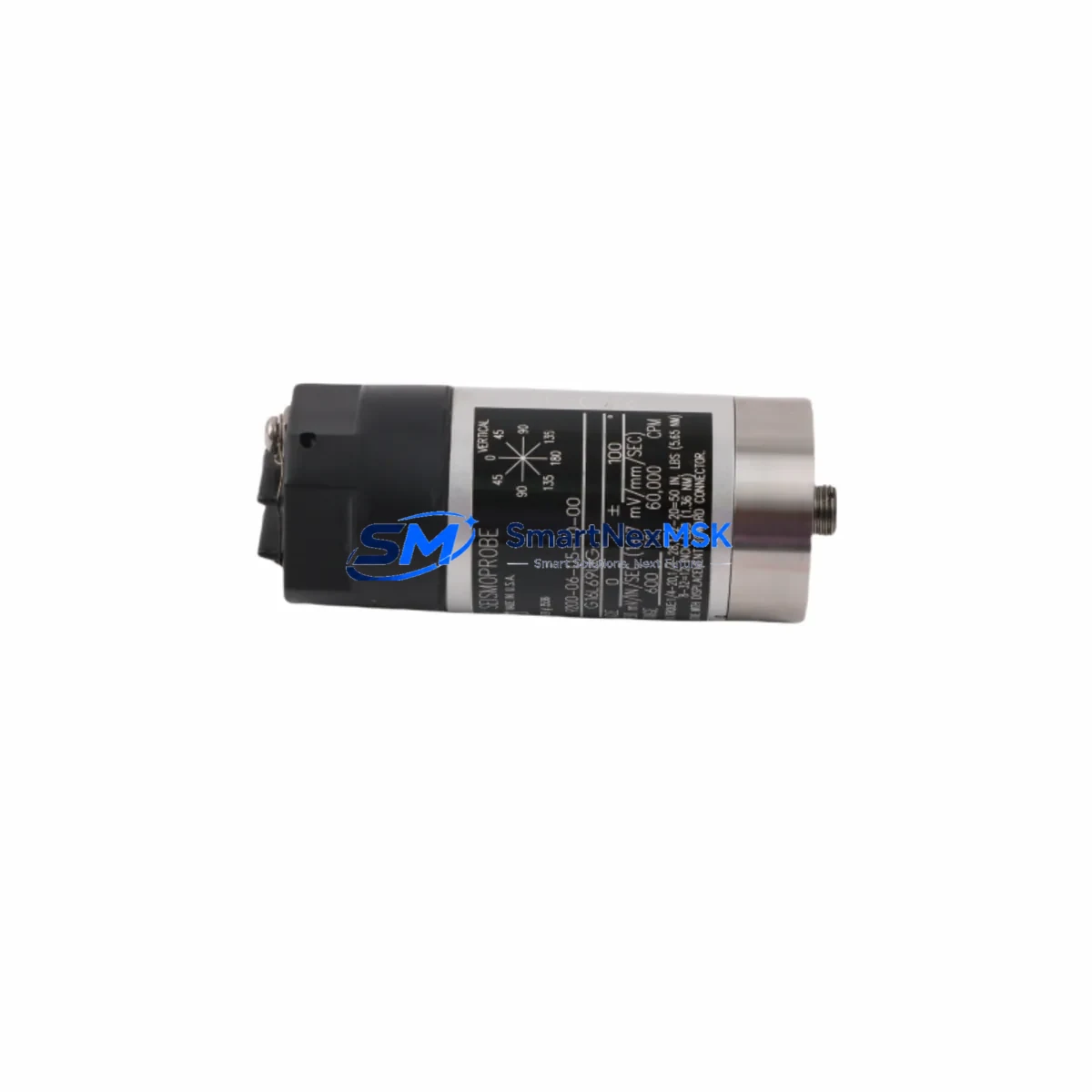
Bently Nevada 9200-06-05-10-00 Spare for 9200 Automation: Spare Replacement & Industrial Downtime Risk Control
The Bently Nevada 9200-06-05-10-00 is a loop-powered, 4–20 mA vibration transducer engineered for continuous machinery health monitoring in rotating equipment applications. Designed for the 9200 Series platform, this transducer delivers reliable vibration amplitude signals to DCS and PLC control systems, enabling predictive maintenance programs and early fault detection on pumps, compressors, fans, and turbines. When this component fails or reaches end-of-life, the consequences extend beyond a single sensor — the entire vibration monitoring loop, alarm logic, and machinery protection chain can be compromised, leading to unplanned downtime and potential equipment damage.
At SMARTNEXMSK, we supply original and compatible 9200-06-05-10-00 units with full pre-shipment functional testing, traceable documentation, and a 12-month warranty. Our inventory is maintained specifically for maintenance engineers and procurement teams who require fast, reliable spare parts fulfillment to support planned shutdowns, emergency replacements, and long-term spares strategies.
Spare Maintenance Table
| Parameter | Specification |
|---|---|
| Part Number | 9200-06-05-10-00 |
| Brand | Bently Nevada |
| Series | 9200 Series |
| Product Type | Loop-Powered Vibration Transducer |
| Output Signal | 4–20 mA (proportional to vibration amplitude) |
| Supply Voltage | 18–30 VDC (loop-powered, 2-wire) |
| Measurement Range | 0–1 in/s pk (typical, velocity output) |
| Frequency Response | 10–1000 Hz (–3 dB) |
| Operating Temperature | –40°C to +85°C |
| Protection Rating | IP67 (dust-tight, water-immersion resistant) |
| Mounting | M8 stud mount / magnetic base compatible |
| Connector | 2-pin M12 industrial connector |
| Compatibility | Bently Nevada 9200 Series monitoring systems; compatible with standard 4–20 mA DCS/PLC input cards |
| Application Environment | Rotating machinery, pumps, compressors, fans, gearboxes, turbines |
| Maintenance Recommendation | Inspect cable integrity and connector seating every 6 months; verify loop current at commissioning and after any panel rewiring |
| Origin | USA |
| Warranty | 12 Months — covers manufacturing defects; includes pre-shipment functional test report |
Maintenance Planning for Continuous Operation
When a 9200-06-05-10-00 vibration transducer is scheduled for replacement during a planned shutdown or emergency callout, experienced maintenance engineers know that the transducer itself is rarely the only component that warrants attention. A thorough inspection of the associated measurement loop and control cabinet is essential to prevent repeat failures and ensure the replaced unit performs to specification from day one.
Begin by verifying the 24 VDC loop power supply feeding the transducer circuit — a degraded or out-of-tolerance supply voltage is a common root cause of erratic 4–20 mA readings that are often misdiagnosed as transducer failure. Check the barrier or isolator module (such as a Bently Nevada 3500/22M I/O module or equivalent signal conditioner) for drift, as these components age in parallel with the transducer and can introduce offset errors after the new sensor is installed.
Inspect the field wiring and M12 connector for corrosion, moisture ingress, and mechanical damage — particularly in outdoor or wash-down environments. Replace the connector if the seal shows any sign of degradation. At the DCS or PLC input card, confirm that the analog input channel (typically a 4–20 mA AI card such as those in the Bently Nevada 3500 rack or a Siemens S7-300/400 SM331 equivalent) is reading correctly against a calibrated loop calibrator before declaring the replacement complete.
For facilities running Bently Nevada 3500 Series machinery protection racks, also verify the 3500/15 power supply module and the 3500/20 rack interface module — both are common failure points in aging systems and should be included in any 9200 Series transducer replacement BOM. If the installation includes a Keyphasor transducer (such as the 3300 XL 8mm proximity probe) for phase reference, confirm its gap voltage and signal quality simultaneously, as phase data is critical for balancing diagnostics triggered by the vibration alarm.
Where the 9200-06-05-10-00 feeds into a relay output module for machinery trip logic, test the relay setpoints and response time after loop restoration. For systems with Modbus RTU or HART communication overlaid on the 4–20 mA loop, re-verify the device address and communication integrity using a handheld communicator. Finally, update the maintenance logbook and CMMS record with the replacement date, loop current at commissioning (typically 12 mA at mid-scale), and the next scheduled inspection interval — typically 12 months or at the next planned outage.
Site Replacement Workflow
Step 1 — Isolation & Safety: De-energize the loop power supply and lock out / tag out (LOTO) the circuit per site safety procedures. Confirm zero energy state with a calibrated multimeter before disconnecting the M12 connector.
Step 2 — Physical Removal: Unscrew the existing 9200-06-05-10-00 from its mounting stud or magnetic base. Note the cable routing and any strain relief arrangements for reinstallation reference.
Step 3 — Inspection: Inspect the mounting surface for corrosion or mechanical damage. Clean the stud threads and verify the mounting torque specification (typically 5–8 Nm for M8 studs). Check the cable for any chafing or pinch points introduced during the previous service life.
Step 4 — Installation: Mount the replacement 9200-06-05-10-00, torque to specification, and reconnect the M12 connector. Restore loop power and measure the loop current with a calibrated loop calibrator — confirm 4 mA at zero vibration (sensor at rest) and verify the DCS/PLC input card reads the correct engineering unit value.
Step 5 — Functional Verification: Apply a known vibration stimulus (or use the system’s built-in test function if available) to confirm the transducer output tracks correctly across the measurement range. Acknowledge any latched alarms in the machinery protection system and confirm normal operating status before returning the machine to service.
Step 6 — Documentation: Record the replacement in the CMMS, attach the pre-shipment test report supplied with the unit, and schedule the next inspection. This workflow is compatible with both legacy 9200 Series installations and modern DCS-integrated monitoring architectures, minimizing downtime to typically under 2 hours for a single-channel replacement.
Spare Parts Support FAQ
Q1: Is the 9200-06-05-10-00 a direct drop-in replacement for older 9200 Series units already installed in the field?
Yes. The 9200-06-05-10-00 maintains dimensional, electrical, and signal compatibility with all standard 9200 Series mounting configurations and 4–20 mA input cards. No reconfiguration of the monitoring system is required for a like-for-like replacement. Always confirm the supply voltage range and connector type against your existing installation drawing before ordering.
Q2: What pre-shipment testing is performed on each unit?
Every 9200-06-05-10-00 supplied by SMARTNEXMSK undergoes a full functional test: loop current verification at 0%, 50%, and 100% of measurement range; insulation resistance check; and connector integrity inspection. A test report is included with each shipment. Units that do not meet factory specification are not dispatched.
Q3: What is the recommended spare parts holding strategy for facilities with multiple 9200 Series installations?
For facilities with 10 or more 9200-06-05-10-00 units installed, we recommend maintaining a minimum of 10% on-hand spares (at least 1–2 units per critical machine train). For remote or offshore installations where lead time is a constraint, a 20% holding is advisable. Combine this with a scheduled replacement program at 5–7 years of continuous service to avoid age-related drift failures.
Q4: What is covered under the 12-month warranty, and how is a warranty claim processed?
The 12-month warranty covers all manufacturing defects, premature component failure under normal operating conditions, and any unit that fails to meet the published specification within the warranty period. To initiate a claim, contact sales@smartnexmsk.com with the order number, installation date, and a brief description of the failure mode. SMARTNEXMSK will arrange return shipping and dispatch a replacement unit within 5 business days of receiving the defective item.
© 2026 SMARTNEXMSK. All rights reserved.
Original Source: https://smartnexmsk.com
Contact: sales@smartnexmsk.com | +86 18259474341


