Bently Nevada 990-04-70-01-00 Spare for 3300 XL Automation: Vibration Transmitter Replacement for Industrial Uptime
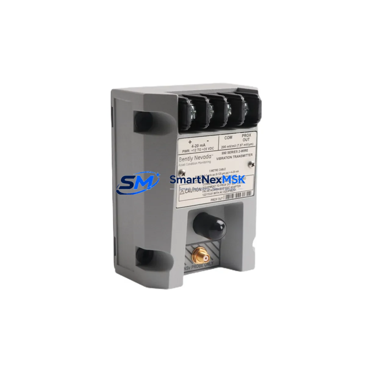
The Bently Nevada 990-04-70-01-00 is a field-mount vibration transmitter engineered for the 3300 XL Series continuous machinery protection system. Designed to convert proximity probe signals into a standard 4–20 mA output, this unit serves as a critical interface between rotating machinery and the plant’s condition monitoring infrastructure. When this transmitter fails or degrades, the entire vibration monitoring loop for that machine train is compromised — leaving operators blind to shaft displacement, bearing wear, and rotor instability events that can escalate into unplanned shutdowns.
For maintenance engineers managing turbines, compressors, pumps, and gearboxes in oil & gas, power generation, petrochemical, and heavy manufacturing environments, having a verified replacement unit of the 990-04-70-01-00 on the shelf is not optional — it is a fundamental element of any credible spare parts strategy. This listing provides an original, tested, and warranty-backed unit ready for immediate deployment.
Spare Maintenance Table
| Parameter | Specification / Detail |
|---|---|
| Part Number / SKU | 990-04-70-01-00 |
| Brand | Bently Nevada |
| Series | 3300 XL Machinery Protection System |
| Product Type | Vibration Transmitter (Field Mount) |
| Output Signal | 4–20 mA (proportional to vibration amplitude) |
| Input Compatibility | 3300 XL Proximitor® / Eddy-Current Probe Systems |
| Mounting Style | Field Mount (DIN rail or panel compatible) |
| Power Supply | 18–30 VDC (loop-powered) |
| Operating Temperature | -40°C to +85°C |
| Origin | United States |
| Condition | Original / Surplus New / Tested |
| Compatibility | 3300 XL Series monitors, 3500 Series rack (with adapter), legacy 3300 systems |
| Application Environment | Rotating machinery: turbines, compressors, pumps, gearboxes |
| Maintenance Recommendation | Replace every 5–8 years or upon signal drift >2% full scale; inspect wiring and probe cable annually |
| Warranty | 12 Months from date of shipment |
| Lead Time | In stock — ships within 1–3 business days |
Maintenance Planning for Continuous Operation
When a 990-04-70-01-00 vibration transmitter is flagged for replacement during a scheduled outage or emergency callout, experienced maintenance engineers know that the transmitter itself is rarely the only component that needs attention. A thorough inspection of the entire vibration monitoring loop and surrounding control cabinet is essential to prevent repeat failures and ensure the replacement unit performs to specification from day one.
Begin with the 3300 XL Proximitor® sensor (such as the 330180 or 330130 series) that feeds the transmitter. Probe gap voltage should be verified with a calibrated meter before the new transmitter is energized — a probe operating outside its linear range will immediately corrupt the 4–20 mA output of the replacement unit. Inspect the probe extension cable and armored conduit for chafing, moisture ingress, or connector corrosion, as these are common sources of intermittent signal faults that are often misdiagnosed as transmitter failure.
At the cabinet level, check the 24 VDC power supply module that feeds the transmitter loop. Voltage sag or ripple above 100 mV can introduce noise into the 4–20 mA signal and trigger nuisance alarms on the 3300 XL monitor. If the cabinet houses a 3300 XL monitor module (such as the 3300/16 or 3300/20), verify that the channel configuration and alarm setpoints are correctly programmed after the transmitter swap — firmware-stored calibration offsets may need to be reset.
For plants running hybrid architectures, the 990-04-70-01-00 output is often wired into a signal isolator or signal conditioner before entering a DCS analog input card. Inspect the isolator for output drift and confirm loop impedance is within the transmitter’s rated load range. Terminal blocks and field wiring at both the junction box and the cabinet marshalling panel should be torqued to spec and checked for oxidation — a common issue in high-humidity or coastal environments.
If the plant’s condition monitoring data feeds into a System 1® Evolution software platform or a third-party historian, verify that the new transmitter’s tag configuration and engineering unit scaling are correctly mapped after commissioning. Plants that have migrated from older 3300 Series to 3300 XL should also confirm that any I/O interface modules or relay output modules in the same rack are functioning correctly, as a failing relay card can mask a genuine vibration alarm even when the transmitter is healthy.
Finally, for facilities managing aging machinery protection systems, it is good practice to simultaneously audit the keyphasor module (if installed) and any temperature monitoring inputs on the same machine train. Vibration and temperature data are often evaluated together during root cause analysis, and a gap in either dataset during a fault event significantly complicates post-incident review.
Site Replacement Workflow
Replacing the 990-04-70-01-00 in the field follows a structured sequence to minimize downtime and ensure system integrity. Before removing the existing unit, document the current 4–20 mA output reading and compare it against the DCS or historian trend to establish a pre-replacement baseline. This baseline is critical for post-installation verification.
De-energize the loop at the field junction box — not at the cabinet — to avoid introducing a false zero signal into the monitor while the cabinet remains live. Remove the transmitter, inspect the terminal connections for corrosion or strand damage, and re-terminate with fresh ferrules if required. Install the 990-04-70-01-00 replacement, restore power, and allow a 5-minute warm-up period before taking readings.
Verify the output current at the cabinet terminals against the known probe gap voltage. If the reading deviates by more than ±0.5 mA from the expected value, re-check probe gap and cable continuity before assuming a transmitter fault. Once confirmed stable, update the maintenance management system (CMMS) with the replacement date, unit serial number, and post-installation readings. This record supports warranty claims and future predictive maintenance scheduling.
For plants transitioning away from legacy 3300 (non-XL) transmitters, the 990-04-70-01-00 is a direct functional replacement in most wiring configurations, though terminal labeling and loop power polarity should be verified against the original wiring diagram before energizing. This compatibility makes the 990-04-70-01-00 a preferred choice for system life extension programs where full rack upgrades are not yet budgeted.
Spare Parts Support FAQ
Q1: What is the recommended spare parts holding quantity for the 990-04-70-01-00 in a large rotating machinery plant?
For facilities with 10 or more monitored machine trains using 3300 XL systems, a minimum of 2 units on-site is recommended. Plants with critical turbines or compressors in continuous service should hold 3–4 units to cover simultaneous failures during a major outage. Given the 12-month warranty from shipment, stock rotation on a 24-month cycle is a practical approach to maintaining warranty coverage on shelf stock.
Q2: How is the 990-04-70-01-00 tested before shipment?
Each unit undergoes functional verification including loop-power energization, 4–20 mA output linearity check across the input range, and insulation resistance testing. Units sourced from original manufacturer surplus channels are additionally inspected for physical condition, connector integrity, and label legibility. A test report is available upon request for critical applications.
Q3: Can the 990-04-70-01-00 be used as a direct replacement for older 3300 Series (non-XL) transmitters?
In most field-mount wiring configurations, yes. The 4–20 mA output and loop-power requirements are compatible with the majority of 3300 Series monitor inputs. However, customers should verify the probe type, gap voltage range, and any site-specific calibration offsets before installation. Our technical team can assist with compatibility confirmation prior to order.
Q4: What does the 12-month warranty cover, and how are warranty claims handled?
The 12-month warranty covers manufacturing defects and functional failure under normal operating conditions as specified in the Bently Nevada 3300 XL documentation. Warranty claims are initiated by contacting our sales team with the order reference, installation date, and a description of the fault. Replacement units are dispatched within 3 business days of claim approval, and failed units are returned for inspection at our cost.
© 2026 SMARTNEXMSK. All rights reserved.
Original Source: https://smartnexmsk.com
Contact: sales@smartnexmsk.com | +86 18259474341


