Bently Nevada 990-04-70-01-05 Retrofit-Ready Vibration Monitor for 990 Series Control Systems
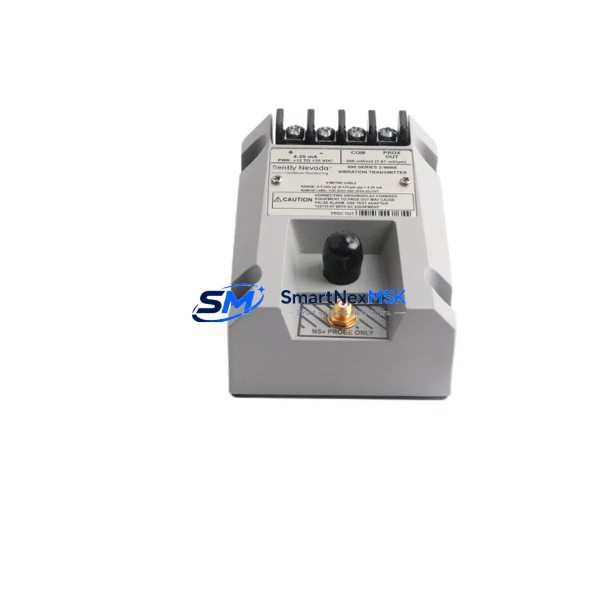
The Bently Nevada 990-04-70-01-05 is a loop-powered, 4–20 mA vibration transmitter engineered for direct integration into existing 990 Series machinery protection and condition monitoring systems. As legacy 990 Series installations approach end-of-support milestones, plant engineers and reliability teams increasingly rely on verified replacement units like the 990-04-70-01-05 to sustain continuous protection without triggering a full-platform migration. This module is stocked, tested, and shipped with a 12-month warranty, making it a dependable choice for both emergency spares and planned retrofit programs.
Whether you are replacing a failed unit on a critical compressor train, upgrading a brownfield control cabinet, or consolidating spare-parts inventory across multiple turbine skids, the 990-04-70-01-05 delivers the electrical and mechanical compatibility required for a low-risk, minimum-downtime swap. The transmitter accepts standard eddy-current probe inputs and outputs a conditioned 4–20 mA signal compatible with the existing 3500 Series rack infrastructure, Bently Nevada TDXnet data concentrators, and third-party DCS platforms including Emerson DeltaV and Honeywell Experion PKS.
Upgrade Compatibility Table
| Parameter | Details |
|---|---|
| SKU / Part Number | 990-04-70-01-05 |
| Brand / Manufacturer | Bently Nevada (Baker Hughes) |
| Series Compatibility | Bently Nevada 990 Series; compatible with 3500 Series rack backplane I/O |
| Signal Output | 4–20 mA loop-powered, two-wire |
| Input Interface | Eddy-current proximity probe (standard 5 mm or 8 mm tip) |
| Mounting / Installation | DIN rail or panel mount; terminal block wiring compatible with existing 990 Series field wiring |
| Communication Compatibility | Analog 4–20 mA; compatible with HART-enabled DCS I/O cards and TDXnet concentrators |
| Replacement Recommendation | Direct drop-in for 990-04-70-01-05; verify gap voltage and scale factor before commissioning |
| Commissioning / Debug Notes | Confirm probe gap (typically –10 VDC at mid-range), check Zener barrier or galvanic isolator compatibility, validate DCS tag scaling and HMI engineering unit range |
| Outgoing Test | 100% functional test performed prior to shipment; test record available on request |
| Warranty | 12 months from date of shipment |
Retrofit Planning for Existing Automation Systems
A successful retrofit of the 990-04-70-01-05 begins well before the unit arrives on site. Start by auditing the existing field wiring: confirm that the two-wire loop cable gauge, shielding, and conduit routing meet the original 990 Series installation requirements. If the cabinet houses a Bently Nevada 3500/42M Proximitor I/O Module or a 3500/40M Proximitor Seismic Monitor, verify that the backplane slot assignment and module address have not drifted from the as-built drawings — address conflicts are a common source of false alerts during commissioning.
Power supply capacity is a critical checkpoint. The 990-04-70-01-05 draws loop power from the DCS or safety system I/O card; confirm that the 24 VDC supply rail — often shared with other field instruments such as Bently Nevada 3500/22M Transient Data Interface cards or third-party pressure transmitters — has sufficient headroom. If the cabinet also contains a Bently Nevada 3500/92 Communication Gateway or a TDXnet data concentrator, those devices add to the rail load and must be accounted for in the power budget calculation. A Bently Nevada 3500/15 Power Supply Module should be verified for available current margin before adding any replacement transmitter to the loop.
For sites running Emerson Ovation or Honeywell Safety Manager as the supervisory layer, the 4–20 mA signal from the 990-04-70-01-05 maps directly to existing analog input channels. However, if the original system used a Bently Nevada 3500/20 Rack Interface Module for digital communication to the DCS, confirm whether the analog fallback path is still active and correctly scaled in the DCS historian. Plants that have partially migrated to Modbus RTU or PROFIBUS DP for vibration data should also verify that the new transmitter output is correctly terminated at the protocol converter or remote I/O gateway.
During the physical swap, label and photograph all terminal connections before disconnecting the old unit. The 990-04-70-01-05 uses the same terminal block pinout as its predecessor, but field wiring that has been modified over years of maintenance may not match the original drawing. Cross-reference the as-built loop diagram against the actual wiring before energizing. If the site uses a Bently Nevada 3500/15 Power Supply Module, confirm that the module is de-energized at the rack level — not just at the field junction box — before removing the transmitter from the cabinet.
HMI screens tied to the vibration channel should be reviewed before returning the loop to service. Operator displays built on Wonderware InTouch, FactoryTalk View SE, or Ignition SCADA typically reference the DCS tag by engineering unit range; if the replacement transmitter has a slightly different scale factor, the HMI bar graph and alarm setpoints will need to be adjusted to prevent nuisance trips. Coordinate with the control room operator to place the affected channel in bypass mode during the swap and restore it only after a successful loop check confirms the 4–20 mA output tracks correctly across the full vibration range. Sites using Bently Nevada System 1 condition monitoring software should also export the pre-swap baseline trend data for the affected machine train so that post-retrofit vibration signatures can be compared immediately after restart.
Downtime Control During System Migration
Minimizing unplanned downtime during a 990-04-70-01-05 replacement requires a structured pre-outage checklist and a clear rollback plan. Before the maintenance window opens, stage the replacement unit alongside a calibrated loop calibrator, a laptop loaded with the current DCS configuration backup, and a copy of the original 990 Series wiring diagram. If the plant operates Bently Nevada System 1 software, export the current baseline trend data for the affected machine train so that post-swap vibration signatures can be compared against the pre-outage baseline immediately after restart.
The actual swap can typically be completed in under 30 minutes for a single transmitter channel, provided the terminal block connections are clearly labeled and the DCS channel is placed in manual or bypass before disconnection. Retain the original program logic in the safety system — do not modify any function block or interlock that references the vibration channel during the swap. The goal is to restore the loop to its pre-fault state with only the physical transmitter changed. Once the new 990-04-70-01-05 is wired and the loop is energized, perform a static gap voltage check at the probe tip and confirm the DCS live value matches the expected engineering unit reading before releasing the channel from bypass.
For multi-channel cabinets where several 990 Series transmitters are being replaced in a single outage, sequence the work channel by channel rather than disconnecting all terminals simultaneously. This approach preserves the remaining channels in service, reduces the risk of wiring errors, and allows the control room to maintain partial machine protection throughout the maintenance window. Document each completed channel with a loop check record and retain it in the plant maintenance management system for future reference and warranty validation. All units supplied by SMARTNEXMSK are shipped with a pre-shipment functional test record and carry a 12-month warranty from the date of delivery.
Retrofit Support FAQ
Q1: Is the 990-04-70-01-05 a direct replacement for the original Bently Nevada part of the same number?
Yes. The unit supplied is a verified equivalent to the original Bently Nevada 990-04-70-01-05 specification, with identical electrical characteristics, terminal pinout, and 4–20 mA signal output range. Each unit undergoes 100% functional testing prior to shipment, and a test record is available upon request. A 12-month warranty is included from the date of delivery.
Q2: What wiring and terminal checks are required before installing the replacement transmitter?
Confirm loop cable continuity and insulation resistance, verify that the 24 VDC supply voltage at the terminal block is within the specified range (typically 18–30 VDC), and check that the cable shield is grounded at one end only. If a Zener barrier or galvanic isolator is installed in the loop, verify its working voltage and current limit are compatible with the 990-04-70-01-05 load requirements before energizing. Photograph all terminal connections before disconnection to support accurate re-wiring.
Q3: How do I verify compatibility with my existing 3500 Series rack and DCS platform?
The 990-04-70-01-05 outputs a standard 4–20 mA signal that is compatible with all 3500 Series I/O modules that accept analog vibration inputs, including the 3500/42M and 3500/40M. For DCS compatibility, confirm that the analog input card — whether Emerson DeltaV, Honeywell Experion, or equivalent — is configured for 4–20 mA input with the correct engineering unit range. No firmware changes to the rack or DCS are required for a like-for-like replacement.
Q4: What does the 12-month warranty cover, and how is a warranty claim processed?
The 12-month warranty covers manufacturing defects and functional failures under normal operating conditions. To initiate a claim, contact our sales team with the order number, installation date, and a description of the fault. Units confirmed defective will be replaced or credited. Warranty does not cover damage resulting from incorrect installation, overvoltage, or physical impact. All units are tested before shipment and include a test record upon request.
© 2026 SMARTNEXMSK. All rights reserved.
Original Source: https://smartnexmsk.com
Contact: sales@smartnexmsk.com | +86 18259474341


