Bently Nevada 990-05-50-01-00 Maintenance-Ready Spare for 990 Series Automation
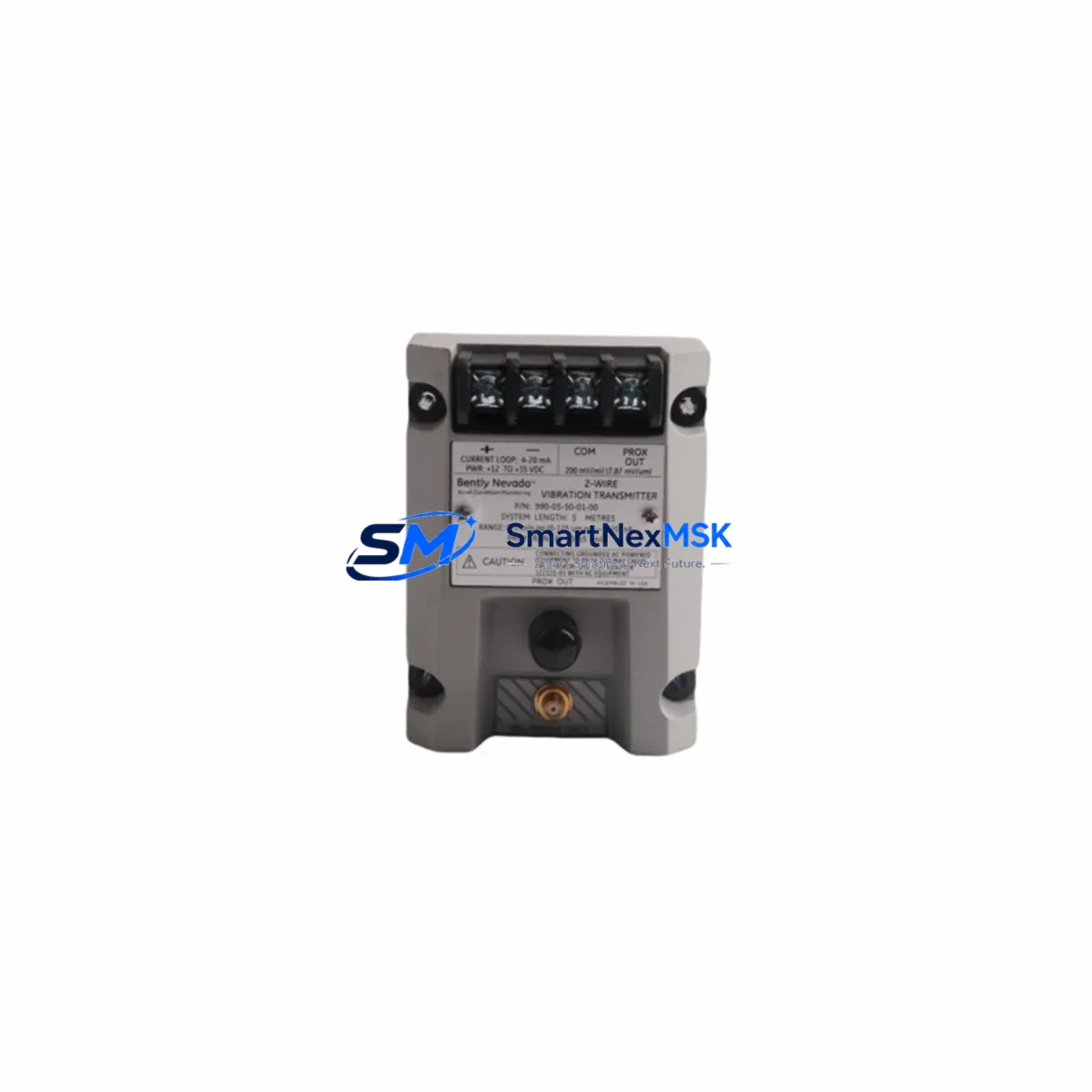
The Bently Nevada 990-05-50-01-00 is a loop-powered vibration transmitter engineered for continuous rotating machinery protection in industrial automation environments. Designed for the 990 Series platform, this original spare delivers a 4–20 mA output signal proportional to overall vibration velocity, making it a direct, drop-in replacement for aging or failed units in turbines, compressors, pumps, motors, and gearboxes. For maintenance engineers managing aging DCS or PLC-based protection systems, having a verified, tested spare of the 990-05-50-01-00 on the shelf is a critical element of any downtime-reduction strategy.
Unplanned vibration transmitter failure is one of the leading causes of unscheduled shutdowns in rotating equipment trains. When a 990-05-50-01-00 fails or drifts out of calibration, the protection loop is compromised — leaving high-value assets exposed to bearing wear, misalignment, or resonance damage without alarm or trip response. Sourcing a pre-tested, original replacement unit from a reliable supplier with documented 12-month warranty coverage is the fastest path to restoring full protection loop integrity and returning the machine to safe operation.
Spare Maintenance Table
| Parameter | Specification |
|---|---|
| Model / SKU | 990-05-50-01-00 |
| Brand | Bently Nevada |
| Series | 990 Series |
| Product Type | Loop-Powered Vibration Transmitter |
| Output Signal | 4–20 mA (2-wire loop-powered) |
| Measurement Parameter | Overall Vibration Velocity (RMS) |
| Frequency Range | 10–1000 Hz (typical) |
| Supply Voltage | 18–30 VDC (loop-powered) |
| Mounting | Stud mount or adhesive pad, standard industrial |
| Housing / Protection | IP65 or better, stainless steel housing |
| Compatibility | Bently Nevada 990 Series, 3500 Series rack I/O, DCS 4–20 mA input cards |
| Application Environment | Turbines, compressors, pumps, motors, gearboxes |
| Origin | USA |
| Condition | Original, new or refurbished-to-spec |
| Warranty | 12 Months |
| Pre-shipment Testing | Signal output, loop integrity, and insulation verified before dispatch |
Maintenance Planning for Continuous Operation
When replacing the 990-05-50-01-00 during a planned or emergency maintenance window, experienced maintenance engineers treat the transmitter swap as an opportunity to audit the entire vibration protection loop and adjacent control cabinet components. A single transmitter failure rarely occurs in isolation — it is often accompanied by degraded wiring, corroded terminal blocks, or marginal power supply performance that will cause the next failure if left unaddressed.
Begin by verifying the 24 VDC loop power supply feeding the transmitter circuit. A sagging or noisy supply rail will cause 4–20 mA signal drift even after a new 990-05-50-01-00 is installed. Check the associated Bently Nevada 3500/42M or 3500/45 vibration monitor module in the 3500 Series rack — these modules receive the 4–20 mA signal and should be inspected for firmware currency and channel calibration. If the rack also houses a 3500/20 rack interface module or a 3500/15 power supply module, verify their status indicators and output voltages as part of the same maintenance cycle.
Inspect the field wiring from the transmitter mounting point back to the control cabinet. Shielded twisted-pair cable is required for 4–20 mA vibration signals; any damaged shielding or improper grounding will introduce noise that mimics real vibration events and can cause nuisance trips. At the cabinet entry, check the terminal blocks — Phoenix Contact or Weidmüller style DIN-rail terminal strips are common in these installations and should be torqued to spec and free of oxidation. Inline signal isolators or barriers, such as a Pepperl+Fuchs KFD2-STC4-Ex1 or equivalent, may be present in hazardous-area installations and should be tested for proper pass-through accuracy.
For sites running a Bently Nevada System 1 condition monitoring platform or integrating vibration data into a Yokogawa CENTUM VP or Emerson DeltaV DCS, confirm that the analog input card receiving the 990-05-50-01-00 signal is correctly ranged (4 mA = 0 mm/s, 20 mA = full-scale velocity). Recalibrate the DCS input tag after transmitter replacement to eliminate any offset error. If the site uses a Modbus RTU or HART gateway to aggregate vibration data, verify the gateway polling configuration has not been disrupted during the maintenance window.
Finally, update the site’s spare parts register to reflect the 990-05-50-01-00 replacement and reorder a buffer stock unit. For rotating equipment trains running 24/7, a minimum of one on-shelf spare per critical machine train is the industry-standard recommendation for vibration transmitters of this class.
Site Replacement Workflow
Step 1 — Isolation and Permit: Obtain a work permit and isolate the loop power supply feeding the 990-05-50-01-00 circuit. Confirm the 4–20 mA loop is de-energized using a calibrated loop tester before disconnecting field wiring.
Step 2 — Document Existing Wiring: Photograph or sketch the terminal connections at both the transmitter and the cabinet terminal block before removal. Note the cable shield grounding point and any ferrite cores or inline barriers in the signal path.
Step 3 — Remove Failed Unit: Unscrew the transmitter from its mounting stud or pad. Inspect the mounting surface for corrosion, cracking, or contamination that could affect the new unit’s vibration coupling accuracy.
Step 4 — Install Replacement 990-05-50-01-00: Mount the new transmitter to the correct torque specification. Reconnect field wiring per the original documentation, ensuring correct polarity on the 2-wire loop. Verify shield continuity and grounding.
Step 5 — Loop Energization and Signal Verification: Re-energize the loop power supply. Using a loop calibrator, inject a known current (e.g., 12 mA = 50% of range) and confirm the DCS or monitor module reads the correct engineering unit value. Check for signal noise or instability.
Step 6 — Functional Test: With the machine running at normal operating speed, confirm the 990-05-50-01-00 output tracks expected vibration levels. Compare readings against historical baseline data in the condition monitoring system. Confirm alarm and trip setpoints are active and correctly configured.
Step 7 — Documentation and Spare Reorder: Record the replacement in the maintenance management system (CMMS). Initiate a purchase order for a replacement buffer stock unit to restore the site’s spare parts inventory to the minimum required level.
Spare Parts Support FAQ
Q1: Is the 990-05-50-01-00 a direct replacement for older 990 Series vibration transmitters?
Yes. The 990-05-50-01-00 is designed as a direct, pin-compatible replacement within the Bently Nevada 990 Series platform. It maintains the same 4–20 mA loop-powered output interface, mounting dimensions, and signal scaling as earlier 990 Series units, allowing field replacement without modification to existing wiring, DCS configuration, or monitor rack settings in the vast majority of installations. Always verify the specific revision suffix and output range against your site documentation before installation.
Q2: What pre-shipment testing is performed on the 990-05-50-01-00 before dispatch?
Each unit undergoes a multi-point inspection prior to shipment: loop output accuracy is verified across the 4–20 mA range using calibrated test equipment, insulation resistance is checked between the loop conductors and housing, and the mechanical mounting interface is inspected for thread integrity and surface condition. A test report is available upon request. All units are dispatched with a 12-month warranty covering manufacturing defects and functional performance.
Q3: How should the 990-05-50-01-00 be stored as a long-term shelf spare?
Store the unit in its original packaging or an equivalent anti-static, moisture-resistant enclosure. Recommended storage conditions are 15–35°C with relative humidity below 75% non-condensing. Avoid storage near strong magnetic fields or vibration sources. Inspect the unit annually for any signs of connector corrosion or seal degradation. Units stored under these conditions maintain full functional specification for a minimum of 5 years from the manufacture date.
Q4: Can the 990-05-50-01-00 be used with third-party DCS or PLC analog input cards?
Yes. Because the 990-05-50-01-00 outputs a standard 4–20 mA loop-powered signal, it is compatible with any industrial analog input card that accepts a 2-wire 4–20 mA transmitter, including cards from Siemens SIMATIC S7, Rockwell Automation ControlLogix, ABB AC500, Schneider Electric Modicon, and Yokogawa CENTUM platforms. Confirm the input card’s loop supply voltage range (typically 18–30 VDC) matches the transmitter’s requirements and that the input impedance is within the transmitter’s specified load resistance limit before installation.
© 2026 SMARTNEXMSK. All rights reserved.
Original Source: https://smartnexmsk.com
Contact: sales@smartnexmsk.com | +86 18259474341


