Bently Nevada 990-05-50-01-CN Spare 990 Series: Vibration Transmitter Replacement for Industrial Downtime Control
The Bently Nevada 990-05-50-01-CN is a field-proven vibration transmitter from the 990 Series, designed for continuous machinery protection in rotating equipment applications including turbines, compressors, pumps, and motors. As a maintenance-ready spare, this unit supports rapid site replacement to minimize unplanned downtime and restore normal operation in DCS and PLC-based control architectures. Each unit supplied by SMARTNEXMSK is sourced from verified channels, functionally tested prior to dispatch, and backed by a 12-month warranty.
For maintenance engineers managing aging control systems or executing planned overhauls, having a pre-qualified 990-05-50-01-CN on the shelf eliminates the lead-time risk that turns a minor fault into an extended production outage. For procurement engineers, this part represents a direct, compatible replacement for the original Bently Nevada specification — no re-engineering, no reconfiguration, no compromise on measurement integrity.
Spare Maintenance Table
| Parameter | Specification |
|---|---|
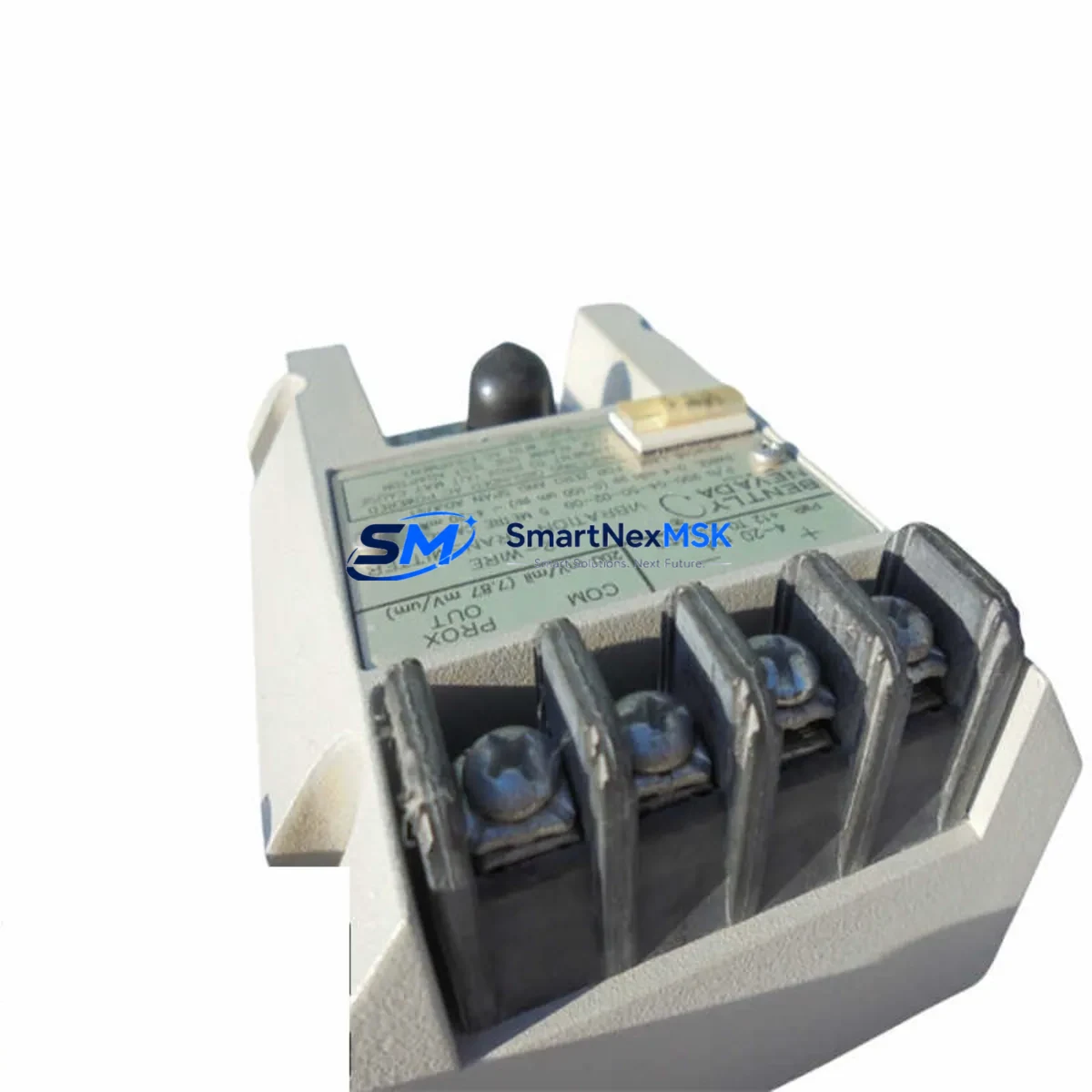
| Part Number | 990-05-50-01-CN |
| Brand | Bently Nevada |
| Series | 990 Series |
| Product Type | Vibration Transmitter |
| Output Signal | 4–20 mA (standard industrial loop) |
| Input Compatibility | Eddy-current proximity probes (3300 XL / 7200 Series) |
| Supply Voltage | 18–30 VDC (loop-powered) |
| Measurement Range | 0–25 mils pp / 0–635 µm pp (configurable) |
| Operating Temperature | -40°C to +85°C |
| Enclosure / Protection | IP66 (field-mount housing) |
| Mounting | DIN rail or panel mount |
| Compatibility | Bently Nevada 3500 System, DCS/PLC 4–20 mA analog input cards |
| Application Environment | Rotating machinery, turbine halls, compressor stations, pump skids |
| Maintenance Recommendation | Inspect wiring, probe gap, and signal cable shielding at each planned outage |
| Warranty | 12 Months — covers functional defects under normal operating conditions |
| Origin | USA |
| Pre-shipment Test | Functional output verification performed before dispatch |
Maintenance Planning for Continuous Operation
Replacing the 990-05-50-01-CN in the field is rarely an isolated task. A thorough maintenance engineer will treat this replacement as an opportunity to audit the entire vibration monitoring loop and the surrounding control cabinet. Begin by verifying the condition of the proximity probe — typically a Bently Nevada 3300 XL 8mm or 3300 XL 11mm eddy-current probe — and its extension cable. A worn or contaminated probe tip will produce erratic 4–20 mA output regardless of transmitter condition, so probe replacement should be evaluated in parallel.
Next, inspect the signal cable shielding and termination at the transmitter input terminals. In high-EMI environments such as motor control centers or VFD-adjacent panels, unshielded or poorly grounded signal cables introduce noise that mimics vibration events. A Bently Nevada 330130 or 330180 series extension cable in good condition is essential for signal integrity.
On the power supply side, confirm that the 24 VDC loop supply — often sourced from a dedicated instrument power supply module or a Bently Nevada 3500/15 Power Supply — is within tolerance and free of ripple. A degraded power supply can cause transmitter drift and false alarms. If the cabinet houses a Bently Nevada 3500/22M Transient Data Interface or a 3500/42M Proximitor I/O Module, verify that the rack backplane connections are secure and that no I/O channel has latched into a fault state.
For DCS-integrated systems, the 4–20 mA signal from the 990-05-50-01-CN typically terminates at an analog input card — such as a Yokogawa AAI141 or an ABB AI810 — through a terminal block or marshalling cabinet. Inspect the terminal strip for corrosion, loose screws, and correct loop resistance. If a signal isolator or barrier (such as a Phoenix Contact MACX MCR or a P+F KFD2-STC4) is installed in the loop, verify its output range and calibration status, as these components age independently of the transmitter.
Where the vibration signal feeds into a safety instrumented system or a machinery protection relay, confirm that the relay trip setpoints and time delays remain correctly configured after the transmitter swap. Any change in transmitter gain or zero offset — even within specification — can shift the effective trip threshold if the relay is not re-verified post-installation.
Finally, for sites running legacy Bently Nevada 3300 Series or older 7200 Series monitoring systems, the 990-05-50-01-CN provides a compatible upgrade path that preserves the existing probe and cabling infrastructure while delivering improved transmitter stability and a current production warranty. This makes it a cost-effective choice for old-system life extension programs where full system replacement is not yet justified.
Site Replacement Workflow
Step 1 — Isolation and Permit: Obtain a work permit and isolate the vibration monitoring loop at the DCS or safety system. Place the affected channel in bypass or maintenance mode to prevent spurious trips during replacement.
Step 2 — Document Existing Configuration: Record the current transmitter tag number, terminal wiring, probe gap voltage (typically -10 to -18 VDC for a correctly gapped 3300 XL probe), and the 4–20 mA output reading at known machine speed. This baseline is essential for post-installation verification.
Step 3 — Remove the Faulty Unit: Disconnect signal and power terminals, label all wires, and remove the 990-05-50-01-CN from its mounting. Inspect the terminal block and housing for moisture ingress or heat damage.
Step 4 — Install the Replacement: Mount the new 990-05-50-01-CN, reconnect terminals per the original wiring diagram, and verify probe gap voltage is within the acceptable window. Apply power and confirm the 4–20 mA output corresponds to the expected vibration level.
Step 5 — Functional Verification: Restore the DCS channel from bypass, confirm the live reading at the operator workstation matches the local transmitter output, and check that no alarms or trips are active. Document the post-installation readings and close the work permit.
Step 6 — Update Spare Parts Register: Log the replaced unit’s serial number, installation date, and the new spare’s details in the site CMMS. Reorder a replacement spare to restore buffer stock — a minimum of one unit per monitored machine train is the recommended inventory posture for critical rotating equipment.
Spare Parts Support FAQ
Q1: Is the 990-05-50-01-CN a direct drop-in replacement for older 990 Series transmitters?
Yes. The 990-05-50-01-CN maintains the same mechanical footprint, terminal layout, and 4–20 mA output characteristic as earlier 990 Series variants. No reconfiguration of the receiving DCS or PLC analog input card is required in standard installations. Verify probe type compatibility (eddy-current, 3300 XL or 7200 Series) before installation.
Q2: What pre-shipment testing is performed on each unit?
Every 990-05-50-01-CN dispatched by SMARTNEXMSK undergoes functional output verification — confirming correct 4–20 mA response across the measurement range — before packaging. Units are shipped with protective packaging to prevent transit damage. A 12-month warranty covers functional defects from the date of receipt.
Q3: How should I manage spare inventory for critical rotating equipment?
For machinery classified as critical (single-train, no installed spare), maintain a minimum of one 990-05-50-01-CN in local stock at all times. For semi-critical or parallel-train equipment, a shared pool of one unit per three to five machines is a common industry practice. SMARTNEXMSK supports long-term supply agreements and repeat orders to help sites maintain consistent buffer stock without over-investment.
Q4: Can this transmitter be used with non-Bently Nevada probes or third-party monitoring systems?
The 990-05-50-01-CN is optimized for use with Bently Nevada eddy-current proximity probes and the associated 3300 or 7200 Series driver electronics. Compatibility with third-party probes depends on the probe’s output impedance and gap voltage characteristics. For integration with non-Bently Nevada DCS or PLC systems, the standard 4–20 mA output is universally compatible with any analog input card accepting a two-wire loop-powered transmitter signal.
© 2026 SMARTNEXMSK. All rights reserved.
Original Source: https://smartnexmsk.com
Contact: sales@smartnexmsk.com | +86 18259474341


