Bently Nevada 990-05-50-02-00 Spare for 990 Series Automation: Spare Replacement & Industrial Downtime Risk Control
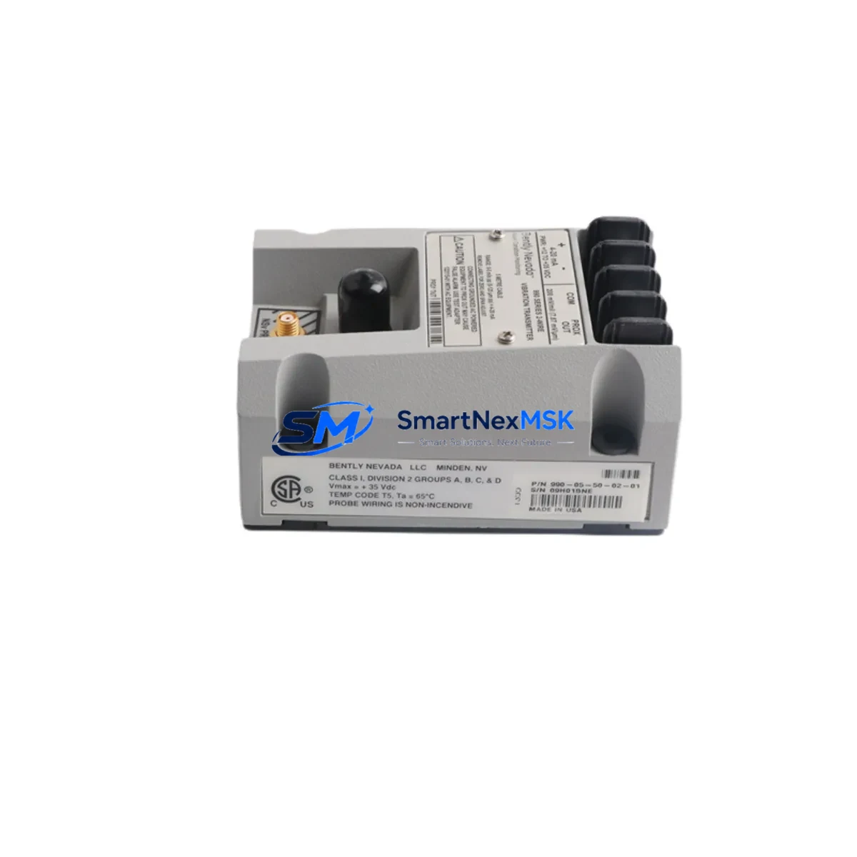
The Bently Nevada 990-05-50-02-00 is a loop-powered 4–20 mA vibration transmitter engineered for continuous machinery protection in rotating equipment applications. As a maintenance-ready original spare, this unit is stocked and tested to support rapid field replacement, minimizing unplanned downtime in turbines, compressors, pumps, and other critical rotating assets monitored by the Bently Nevada 990 Series platform.
For maintenance engineers managing aging machinery protection systems, the 990-05-50-02-00 represents a direct-fit replacement that preserves signal integrity and system compatibility without requiring reconfiguration of the host monitoring rack. Procurement engineers sourcing spare parts for long-term maintenance contracts will find this unit available with verified origin documentation, pre-shipment functional testing, and a 12-month warranty covering manufacturing defects and operational failure under normal service conditions.
Whether you are executing a planned shutdown inspection, responding to a vibration alarm, or building a strategic spare parts inventory for a critical asset, the 990-05-50-02-00 is a proven component that supports both corrective and preventive maintenance strategies across a wide range of industrial environments.
Spare Maintenance Table
| Parameter | Specification |
|---|---|
| Part Number / SKU | 990-05-50-02-00 |
| Brand | Bently Nevada |
| Series | 990 Series |
| Product Type | Vibration Transmitter |
| Output Signal | 4–20 mA (loop-powered) |
| Measurement Type | Velocity / Vibration (seismic) |
| Frequency Range | Typically 10–1000 Hz (series standard) |
| Power Supply | Loop-powered, 18–30 VDC |
| Output Load | ≤ 600 Ω at 24 VDC |
| Operating Temperature | -40°C to +85°C |
| Enclosure / Protection | IP65 (field-mount rated) |
| Mounting | Direct stud mount or adapter plate |
| Compatibility | Bently Nevada 3500 Series rack, 990 Series monitors, DCS 4–20 mA input cards |
| Origin | USA (Original Bently Nevada) |
| Condition | New / Original Spare |
| Pre-shipment Testing | Functional output verification performed |
| Warranty | 12 Months |
| Lead Time | In stock — ships within 2 business days |
| Application Environment | Turbines, compressors, pumps, fans, gearboxes |
| Maintenance Recommendation | Replace at first sign of signal drift, output clamp, or physical damage; inspect mounting surface and cable shield continuity during replacement |
Maintenance Planning for Continuous Operation
When replacing the 990-05-50-02-00 vibration transmitter during a planned or emergency maintenance event, a thorough inspection of the surrounding electrical circuit is essential to ensure the root cause of failure is addressed and the replacement unit is not exposed to the same fault conditions.
Begin by verifying the integrity of the field wiring and cable shield between the transmitter and the DCS or PLC analog input card. Damaged shielding or ground loops are a common cause of signal noise and premature transmitter failure. Inspect the 24 VDC loop power supply — typically sourced from a dedicated instrument power distribution module — for correct voltage output and ripple within specification. A degraded power supply can cause erratic 4–20 mA output even from a new transmitter.
Check the analog input card on the host monitoring system, such as a Bently Nevada 3500/42M Proximitor/Seismic Monitor card or a compatible DCS I/O module, for correct channel configuration and input impedance. If the system uses a signal isolator or signal conditioner between the transmitter and the control system, verify that the isolator’s loop burden and isolation voltage ratings are still within specification — these components degrade over time and can introduce offset errors.
During cabinet inspection, also examine the terminal blocks and field junction box for corrosion, loose terminations, or moisture ingress. In high-vibration environments, terminal screws can loosen over time, causing intermittent signal loss that is often misdiagnosed as transmitter failure. Inspect any in-line fuses or circuit breakers protecting the instrument loop for correct rating and continuity.
If the 990-05-50-02-00 is part of a larger machinery protection system, consider simultaneously auditing adjacent proximity probes, Keyphasor transducers, and accelerometers connected to the same monitoring rack. A single vibration event that damages one transmitter may have also stressed nearby sensors or their extension cables. For systems using a Bently Nevada 3500 Series rack, verify that the rack’s power supply module and I/O module firmware are current and that no latent alarms are masked in the system configuration.
Procurement engineers building a strategic spare parts list for rotating equipment maintenance should consider stocking companion items such as 3500/42M monitor cards, 330130 proximity probes, 330180 extension cables, 3500/15 power supply modules, and appropriate field junction boxes to support rapid system restoration across multiple failure scenarios.
Site Replacement Workflow
Step 1 — Isolation and Permit: Obtain a work permit and isolate the instrument loop at the field junction box or marshalling cabinet. Confirm loop de-energization with a calibrated multimeter before disconnecting the transmitter.
Step 2 — Physical Removal: Disconnect the field cable from the transmitter terminals, noting wire labeling and shield termination method. Remove the transmitter from its mounting stud or adapter plate. Inspect the mounting surface for corrosion or thread damage and clean as required.
Step 3 — Replacement Unit Verification: Confirm the replacement 990-05-50-02-00 part number, serial number, and test certificate against the purchase documentation. Verify the unit has not been exposed to physical shock or moisture during storage.
Step 4 — Installation: Mount the replacement transmitter to the correct torque specification. Reconnect field wiring per the original termination diagram, ensuring the cable shield is terminated at one end only (typically at the control cabinet) to prevent ground loops.
Step 5 — Loop Commissioning: Re-energize the loop and verify the transmitter output at the DCS or monitoring rack. Confirm the 4 mA zero-signal output at rest and check for correct scaling at the host system. Document the as-found and as-left readings in the maintenance management system.
Step 6 — System Restoration: Clear any latched alarms at the monitoring rack, restore the system to normal operating mode, and confirm that vibration trend data is being logged correctly. Update the spare parts inventory record to reflect the consumed unit and initiate a replenishment order to maintain minimum stock levels.
This workflow is applicable to both emergency corrective replacements and scheduled preventive maintenance intervals, and is designed to minimize total downtime from fault detection to system restoration.
Spare Parts Support FAQ
Q1: What is the expected service life of the 990-05-50-02-00, and when should it be replaced proactively?
The 990-05-50-02-00 is designed for long-term continuous service in industrial environments. Proactive replacement is recommended when the unit exhibits signal drift exceeding ±0.5 mA from the calibrated baseline, when physical damage to the housing or cable entry is observed, or when the unit has been exposed to a process upset or electrical fault event. For critical assets, a planned replacement interval of 5–8 years is a common industry practice, aligned with major turnaround schedules.
Q2: How do I verify compatibility before installation in my existing 990 Series or 3500 Series system?
Confirm the host monitor’s input channel type (velocity/seismic), input impedance, and loop supply voltage against the 990-05-50-02-00 datasheet. The unit is designed for direct compatibility with Bently Nevada 990 Series monitors and 3500/42M seismic monitor cards configured for 4–20 mA velocity input. If your system uses a third-party DCS analog input card, verify the card’s input impedance is ≤ 600 Ω at the available loop voltage.
Q3: What pre-shipment testing is performed on each unit, and what documentation is provided?
Each 990-05-50-02-00 unit undergoes functional output verification prior to shipment, confirming correct 4–20 mA output across the operating range. Units are shipped with a test record and original manufacturer documentation where available. A certificate of conformance is provided upon request. All units are covered by a 12-month warranty from the date of shipment.
Q4: Can you support long-term supply agreements for this part number?
Yes. We maintain ongoing stock of the 990-05-50-02-00 and can support blanket purchase orders, scheduled delivery agreements, and consignment stock arrangements for maintenance organizations managing large rotating equipment fleets. Contact our technical sales team to discuss volume pricing, lead time commitments, and spare parts kitting options tailored to your maintenance program.
—
© 2026 SMARTNEXMSK. All rights reserved.
Original Source: https://smartnexmsk.com
Contact: sales@smartnexmsk.com | +86 18259474341


