Bently Nevada 990-05-71-01-05 Maintenance-Ready Spare 990 Series: Spare Replacement & Industrial Downtime Risk Control
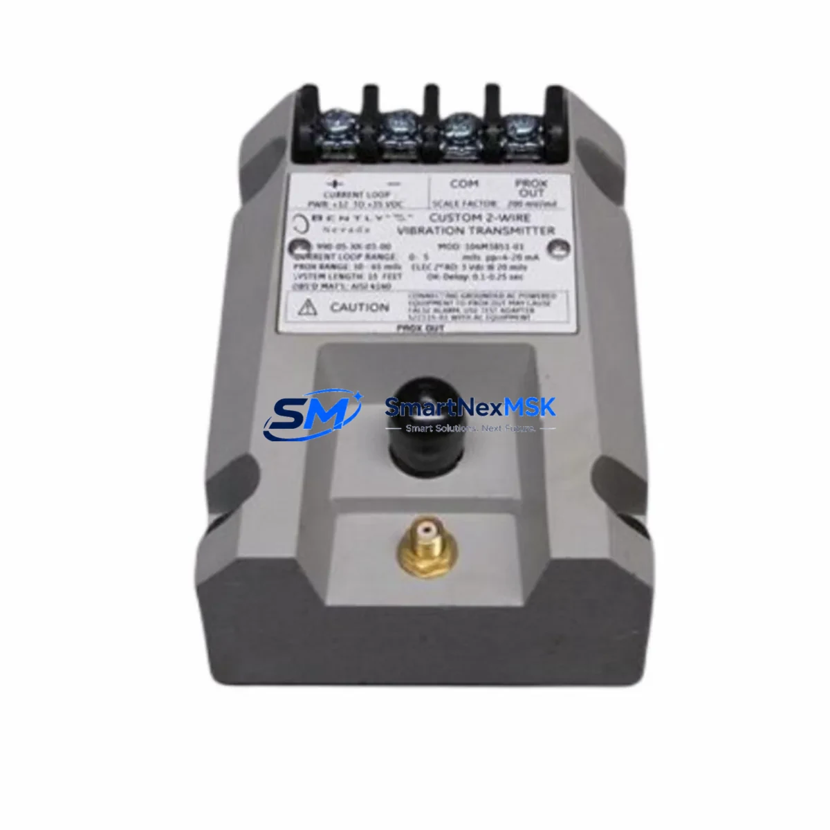
The Bently Nevada 990-05-71-01-05 is a 4–20 mA loop-powered vibration transmitter from the 990 Series, engineered for continuous machinery health monitoring in rotating equipment applications including turbines, compressors, pumps, and motors. As a maintenance-ready original spare, this unit is sourced, inspected, and dispatched to support rapid field replacement, minimizing unplanned downtime in critical industrial processes. Each unit is functionally tested prior to shipment and backed by a 12-month warranty, making it a reliable choice for both planned maintenance schedules and emergency spare parts procurement.
For maintenance engineers managing aging Bently Nevada monitoring systems, the 990-05-71-01-05 represents a direct-fit replacement that preserves existing wiring, loop configurations, and DCS integration without requiring system reconfiguration. Its compatibility with the 990 Series architecture ensures that signal integrity, measurement range, and output characteristics remain consistent with the original installation specification.
Spare Maintenance Table
| Parameter | Specification |
|---|---|
| Part Number / SKU | 990-05-71-01-05 |
| Brand | Bently Nevada |
| Series | 990 Series |
| Product Type | Vibration Transmitter |
| Output Signal | 4–20 mA (loop-powered) |
| Measurement Type | Vibration (velocity/acceleration, application-dependent) |
| Power Supply | Loop-powered (24 VDC nominal) |
| Compatibility | Bently Nevada 990 Series monitoring systems; compatible with standard 4–20 mA DCS/PLC input cards |
| Installation | Direct replacement for existing 990-05-71-01-05 installations; no rewiring required |
| Application Environment | Industrial plant environments; rotating machinery, turbines, compressors, pumps |
| Origin | United States |
| Pre-shipment Testing | Functional output verification performed on each unit |
| Warranty | 12 Months |
| Shipping | Global express; secure anti-static packaging |
| Maintenance Recommendation | Inspect loop wiring, terminal blocks, and associated signal conditioners during replacement |
Maintenance Planning for Continuous Operation
When scheduling replacement of the 990-05-71-01-05 vibration transmitter, a thorough site inspection of the surrounding measurement loop is essential to ensure the new unit performs to specification from the moment it is commissioned. Maintenance engineers should begin by verifying the 24 VDC loop power supply and confirming that the power supply module feeding the transmitter circuit is within its rated output tolerance. Voltage fluctuations or ripple from an aging power supply can introduce measurement error or cause premature failure of the replacement transmitter.
Next, inspect all field wiring and terminal blocks associated with the transmitter loop. Corroded terminals, loose connections, or degraded cable insulation are common root causes of intermittent signal faults that are often misattributed to the transmitter itself. If the installation includes a Bently Nevada 3500 Series rack or a compatible monitoring module, verify that the input card’s 4–20 mA channel is functioning correctly before installing the replacement unit — a faulty input card will mask the performance of an otherwise healthy transmitter.
For sites running integrated machinery protection systems, it is advisable to simultaneously inspect the associated keyphasor module and any proximity probe drivers connected to the same monitoring rack. These components share the same measurement philosophy and are subject to similar environmental stresses. If the 990-05-71-01-05 has failed due to vibration fatigue or moisture ingress, adjacent proximity probes and extension cables should be evaluated for similar degradation.
Signal isolators and barriers installed between the transmitter and the DCS or PLC analog input card should also be checked. A Zener barrier or galvanic isolator that has drifted out of calibration will distort the 4–20 mA signal and produce inaccurate vibration readings even with a new transmitter in place. Where the system includes a safety instrumented function, confirm that the SIL-rated isolator remains within its proof-test interval.
Procurement engineers building a spare parts inventory for 990 Series installations should consider stocking complementary components alongside the 990-05-71-01-05: a spare 3500/42M proximitor/seismic monitor module, replacement BNC-to-terminal adapters, a set of 3300 XL 8mm proximity probes, and at least one spare analog input card compatible with the site’s DCS platform. For sites with older Bently Nevada 7200 Series or 3300 Series installations, cross-referencing the transmitter’s signal output with the existing monitoring card’s input range is a critical compatibility step before ordering.
Control cabinet inspections during planned maintenance windows should include a check of the fuse holders and miniature circuit breakers protecting the transmitter loop, as well as a review of the terminal strip labeling to confirm loop identification remains accurate. Where HMI displays are used to visualize vibration trends, verify that the engineering unit scaling on the HMI tag matches the transmitter’s calibrated output range to avoid misinterpretation of alarm thresholds.
Site Replacement Workflow
Step 1 — Isolation and Permit: Obtain a work permit and isolate the transmitter loop at the field junction box. Confirm loop power is de-energized before disconnecting the transmitter. For live-maintenance scenarios where the process cannot be interrupted, consult the site’s hot-work procedure for loop-powered instruments.
Step 2 — Documentation: Record the existing terminal wiring configuration, cable tag numbers, and loop identification before removal. Photograph the installation if the wiring layout is complex. Confirm the replacement unit’s part number (990-05-71-01-05) matches the installed item exactly, including any suffix codes that indicate output range or housing variant.
Step 3 — Physical Replacement: Remove the failed transmitter and inspect the mounting surface and conduit entry for moisture or mechanical damage. Install the replacement 990-05-71-01-05 using the original mounting hardware where possible. Reconnect wiring per the recorded configuration, ensuring correct polarity on the 4–20 mA loop terminals.
Step 4 — Loop Verification: Re-energize the loop and confirm the transmitter output at the DCS or monitoring system. A 4 mA signal at zero vibration and a proportional increase under a known vibration input confirms correct installation. If a HART communicator is available, use it to verify the transmitter’s configuration parameters and confirm the output is within calibration tolerance.
Step 5 — System Handback: Clear any latched alarms in the monitoring system, confirm trend data is being recorded correctly, and update the maintenance management system (CMMS) with the replacement date, new unit serial number, and next planned inspection interval. Retain the failed unit for failure analysis if root cause investigation is required.
This workflow is applicable to direct replacement of legacy 990-05-71-01-05 units in existing installations and supports system compatibility without firmware changes, recalibration of the monitoring rack, or modification of DCS tag configurations.
Spare Parts Support FAQ
Q1: Is the 990-05-71-01-05 a direct replacement for all 990 Series vibration transmitter variants?
The 990-05-71-01-05 is a specific part number within the 990 Series and is a direct replacement for units carrying the same suffix code. Before ordering, confirm that the installed unit’s full part number matches, as suffix codes in the 990 Series denote differences in output range, housing type, or approval rating. If you are replacing a unit with a different suffix, contact our technical team to confirm cross-compatibility before installation.
Q2: What pre-shipment testing is performed on each unit?
Every 990-05-71-01-05 unit is functionally tested prior to dispatch. Testing includes loop output verification across the 4–20 mA range and a visual inspection for physical damage. Units are packaged in anti-static, shock-resistant materials to maintain condition during international transit. A test report is available upon request for quality-critical applications.
Q3: How should I manage long-term spare parts inventory for 990 Series installations?
For sites with multiple 990 Series transmitters, we recommend maintaining a minimum of one spare 990-05-71-01-05 per critical measurement loop, with a review cycle aligned to your planned maintenance intervals. Given that the 990 Series is a mature product line, long-term supply availability should be confirmed with your supplier annually. We maintain stock continuity and can support blanket orders or scheduled releases to align with your site’s maintenance calendar.
Q4: What is covered under the 12-month warranty?
The 12-month warranty covers manufacturing defects and functional failures under normal operating conditions. It does not cover damage resulting from incorrect installation, overvoltage, mechanical impact, or operation outside the specified environmental ratings. Warranty claims are supported by our technical team, and replacement units are dispatched promptly upon confirmation of a valid warranty fault. For sites requiring extended warranty coverage or on-site support agreements, please contact us directly.
© 2026 SMARTNEXMSK. All rights reserved.
Original Source: https://smartnexmsk.com
Contact: sales@smartnexmsk.com | +86 18259474341


