Bently Nevada 990-05-XX-01-00 3300 XL Vibration Transmitter: Retrofit-Ready Upgrade for Legacy Machinery Protection Systems
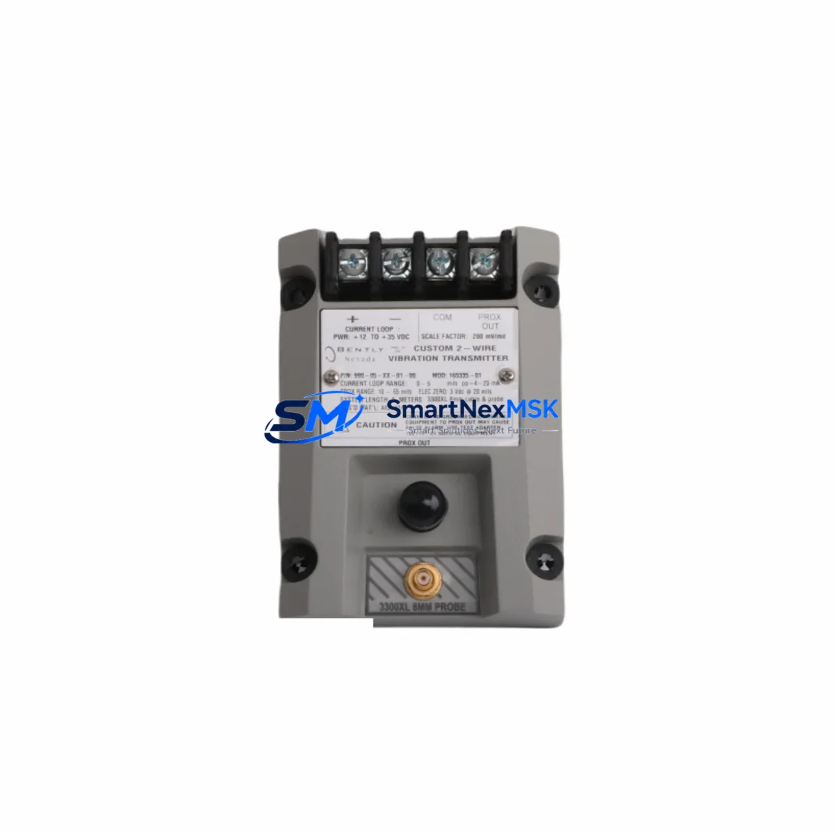
The Bently Nevada 990-05-XX-01-00 (also catalogued as 165335-01) is a precision vibration transmitter engineered for the 3300 XL Machinery Protection System platform. Designed to deliver a standard 4–20 mA analog output proportional to shaft vibration amplitude, this module serves as a direct retrofit replacement for aging or discontinued transmitter assemblies across rotating machinery applications including turbines, compressors, pumps, and gearboxes. Whether you are restoring a legacy protection rack, upgrading a control cabinet, or migrating from an earlier 3300 series configuration, the 990-05-XX-01-00 provides a validated, drop-in compatible solution with minimal re-engineering.
Industrial facilities operating continuous-process equipment cannot afford extended downtime for instrumentation upgrades. The 990-05-XX-01-00 is stocked and tested to support rapid deployment, with each unit undergoing functional verification prior to shipment. A 12-month warranty covers all supplied modules, giving procurement and maintenance teams confidence in both quality and supply continuity.
Upgrade Compatibility Table
| Parameter | Details |
|---|---|
| Part Number | 990-05-XX-01-00 / 165335-01 |
| Series | Bently Nevada 3300 XL Machinery Protection System |
| Output Signal | 4–20 mA analog (proportional to vibration amplitude) |
| Mounting / Installation | DIN-rail or rack-mount per 3300 XL backplane specification |
| Backplane Interface | Compatible with 3300 XL rack backplane; verify slot addressing before installation |
| Communication Compatibility | Analog 4–20 mA; integrates with DCS, PLC, and SCADA via standard I/O cards |
| Replacement Guidance | Direct replacement for legacy 3300 series vibration transmitters; confirm terminal wiring map before swap |
| Commissioning Notes | Verify transducer supply voltage, gap voltage, and OK relay setpoints post-installation |
| Warranty | 12 months from date of shipment |
Retrofit Planning for Existing Automation Systems
Successful integration of the 990-05-XX-01-00 into an existing machinery protection rack begins with a thorough review of the installed 3300 XL system architecture. Technicians should first document the current rack configuration, noting the positions of the 3300/16-channel I/O module, the 3300/55 power supply module, and any 3300/20 proximitor I/O modules already in service. The backplane slot address assigned to the outgoing transmitter must be preserved or remapped in the system configuration software to avoid alarm logic conflicts.
Terminal wiring is a critical checkpoint. The 990-05-XX-01-00 uses a standard Bently Nevada terminal block layout; however, field wiring from the 3300/05 proximitor or eddy-current transducer must be verified against the replacement module’s pinout diagram. Pay particular attention to the transducer power supply lead, the OK relay output, and the 4–20 mA signal return path. Where the existing installation uses a 3300/46 Keyphasor module for phase-reference measurements, confirm that the Keyphasor signal routing to the new transmitter is intact and that the gap voltage is within the –10 to –18 VDC acceptance window.
For facilities running a distributed control system, the 4–20 mA output from the 990-05-XX-01-00 typically terminates at an analog input card within the DCS or at a dedicated vibration monitoring I/O module. If the upstream system is a Bently Nevada System 1 software platform, re-establish the channel configuration and engineering unit scaling after module replacement. Where a PLC-based safety interlock reads the vibration signal, verify that the new module’s output range and fault-state behavior match the interlock logic expectations before returning the machine to service.
Control cabinet upgrades that include the 990-05-XX-01-00 often coincide with replacement of the 3300/15 power supply or addition of a 3300 XL expansion rack. In these scenarios, confirm that the total current draw on the backplane does not exceed the power supply rating. If the cabinet also houses an HMI panel linked to the machinery protection system, update the HMI tag database to reflect any channel address changes, and validate that vibration trend displays and alarm annunciation screens reflect accurate engineering units after commissioning.
Downtime Control During System Migration
Minimizing production interruption during a vibration transmitter swap requires advance preparation. Before the maintenance window opens, stage the replacement 990-05-XX-01-00 alongside a printed copy of the existing terminal wiring schedule, the rack slot map, and the current alarm setpoint list exported from the System 1 configuration database. Where possible, perform a hot-standby comparison: record the live 4–20 mA output value from the outgoing module under normal operating conditions so that the replacement module’s output can be validated against a known baseline immediately after installation.
During the swap, inhibit the vibration alarm outputs at the DCS or safety system level to prevent spurious trips while the channel is open. Restore the transducer wiring, confirm gap voltage, and re-enable the OK relay before lifting the alarm inhibit. For critical machinery where even a brief unmonitored period is unacceptable, a temporary portable vibration analyzer connected to the transducer cable can maintain continuous monitoring throughout the module exchange. Once the 990-05-XX-01-00 is energized and the output is confirmed stable, restore all alarm setpoints, document the as-left configuration, and update the maintenance management system with the new module serial number and installation date.
Retrofit Support FAQ
Q1: Is the 990-05-XX-01-00 a direct drop-in replacement for earlier 3300 series vibration transmitters?
In most installations, yes. The 990-05-XX-01-00 is designed to fit the 3300 XL rack backplane and uses the same terminal block footprint as predecessor modules. However, always compare the terminal wiring diagram of the outgoing module with the replacement before disconnecting field cables, as minor pinout revisions may exist between hardware revisions.
Q2: What commissioning checks are required after installation?
After seating the module and reconnecting field wiring, verify transducer gap voltage (typically –10 to –18 VDC for eddy-current probes), confirm the OK relay energizes under normal vibration conditions, and validate the 4–20 mA output against a known vibration reference. Update the System 1 or DCS channel configuration if the module address has changed.
Q3: Can this module communicate with a PLC or SCADA system?
Yes. The 990-05-XX-01-00 provides a standard 4–20 mA analog output that connects directly to any analog input card in a PLC, DCS, or SCADA I/O subsystem. No special communication protocol is required; the signal is compatible with all major control platforms used in industrial process and power generation facilities.
Q4: What does the 12-month warranty cover?
The warranty covers manufacturing defects and functional failures under normal operating conditions for 12 months from the date of shipment. Each unit is functionally tested prior to dispatch. For warranty claims or technical support, contact our team directly.
© 2026 SMARTNEXMSK. All rights reserved.
Original Source: https://smartnexmsk.com
Contact: sales@smartnexmsk.com | +86 18259474341


