Bently Nevada 990-05-XX-01-00 Maintenance-Ready Spare for 3500 Automation
The Bently Nevada 990-05-XX-01-00 is a precision vibration transmitter module engineered for continuous integration within the 3500 Series machinery protection system. For maintenance engineers managing rotating equipment — turbines, compressors, pumps, and motors — this module is a critical line-of-defense component. Its role in real-time vibration monitoring means that any failure or degradation directly threatens uptime, process safety, and regulatory compliance. Stocking a verified original spare of the 990-05-XX-01-00 is not optional in high-availability plant environments; it is a fundamental element of any credible maintenance strategy.
When a vibration transmitter fails or drifts out of calibration, the window for safe, controlled replacement is narrow. Unplanned downtime in rotating machinery environments can cascade rapidly — from a single tripped channel to a full machinery protection system alarm, forcing emergency shutdown. The 990-05-XX-01-00 is designed for rapid field swap within the 3500 rack architecture, minimizing mean time to repair (MTTR) and restoring monitoring coverage without requiring system reconfiguration or software re-parameterization.
From a procurement engineering perspective, sourcing this module from a reliable supplier with documented testing, original packaging, and a 12-month warranty eliminates the risk of counterfeit or refurbished parts entering the critical spares inventory. Every unit shipped by SMARTNEXMSK undergoes pre-shipment functional verification to confirm output signal integrity, loop power compatibility, and connector condition before dispatch.
Spare Maintenance Table
| Parameter | Specification / Detail |
|---|---|
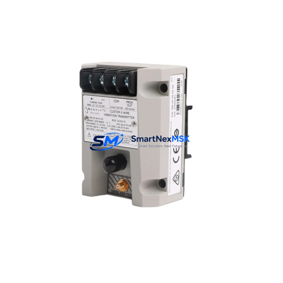
| Part Number | 990-05-XX-01-00 |
| Brand | Bently Nevada |
| Series | 3500 Series Machinery Protection System |
| Module Type | Vibration Transmitter |
| Output Signal | 4–20 mA (industry standard loop) |
| Supply Voltage | 18–30 VDC (loop-powered) |
| Compatibility | 3500/42M, 3500/44M, 3500/45, 3500/46M rack slots; compatible with 3500 System Monitor and Rack Interface Module |
| Installation | Direct rack insertion; no tools required for module swap |
| Operating Temperature | -40°C to +70°C |
| Application Environment | Industrial plant floor, control room rack, hazardous area (check ATEX/IECEx variant suffix) |
| Origin | United States |
| Condition | Original, new or tested-serviceable |
| Warranty | 12 Months from date of shipment |
| Pre-Shipment Test | Signal output, loop integrity, connector inspection |
| Lead Time | In-stock: ships within 1–3 business days |
Maintenance Planning for Continuous Operation
Replacing the 990-05-XX-01-00 in a live 3500 rack is rarely an isolated task. Experienced maintenance engineers know that a vibration transmitter fault often signals broader stress on the monitoring loop and adjacent components. A disciplined replacement workflow should include inspection of the following systems and components:
Begin with the 3500 Rack Interface Module (RIM) and 3500 System Monitor — these govern rack-level communication and power distribution. A degraded RIM can cause intermittent channel faults that mimic transmitter failure. Next, verify the 3500/15 Power Supply Module output rails; voltage sag or ripple on the 24 VDC bus will affect transmitter accuracy and loop stability across all installed channels.
Inspect the field wiring terminal blocks and Bently Nevada 3500 I/O module associated with the affected channel. Corroded terminals, loose ferrules, or damaged shielding on the signal cable between the transmitter and the proximitor/sensor are common root causes of apparent transmitter faults. The 3300 XL 8mm proximitor system or 330180 proximity transducer connected upstream should be verified for gap voltage and sensitivity before the new 990-05-XX-01-00 is commissioned.
For systems using Bently Nevada 3500/22M Transient Data Interface or 3500/72M Process Variable Monitor, confirm that channel configuration files are backed up before module swap — some firmware versions require re-upload of configuration data after a cold replacement. If the plant uses a DCS integration via 4–20 mA or Modbus, validate the signal at the DCS input card after replacement to confirm loop continuity end-to-end.
Where the 3500 rack feeds into a GE System 1 Evolution or similar condition monitoring platform, re-verify the channel mapping and alarm setpoints post-replacement. Finally, check the 3500/92 Communication Gateway Module if Ethernet or serial communication to the plant historian is part of the monitoring architecture — a module swap can occasionally trigger a communication timeout that requires a gateway reset.
Maintaining a minimum of two units of the 990-05-XX-01-00 in the critical spares cabinet — alongside matched proximitor cables, a spare power supply module, and a set of terminal block connectors — is the recommended posture for any plant operating rotating machinery under continuous protection.
Site Replacement Workflow
Step 1 — Isolation and Documentation: Before removing the 990-05-XX-01-00, document the current channel configuration, alarm setpoints, and OK relay status from the 3500 System Monitor. Take a photograph of the wiring terminations on the associated I/O module.
Step 2 — Module Removal: With the rack in bypass mode (or channel inhibited via the System Monitor), carefully extract the faulty transmitter module. Inspect the backplane connector for bent pins or contamination before inserting the replacement unit.
Step 3 — Replacement Installation: Insert the new 990-05-XX-01-00 firmly into the rack slot. Confirm the OK LED illuminates and the System Monitor acknowledges the module. Restore channel inhibit status.
Step 4 — Signal Verification: Using a calibrated loop calibrator or the plant DCS, verify the 4–20 mA output corresponds to the actual vibration level at the measurement point. Compare against the adjacent channel or a portable vibration analyzer for cross-reference.
Step 5 — Alarm Reinstatement: Re-enable all alarm and danger setpoints. Confirm OK relay output is healthy. Log the replacement in the plant CMMS with the new module serial number and date of installation.
This workflow is compatible with legacy 3500 rack installations and does not require a full system shutdown, making it suitable for hot-standby or redundant rack configurations where continuous protection must be maintained throughout the maintenance event.
Spare Parts Support FAQ
Q1: Is the 990-05-XX-01-00 compatible with all 3500 Series rack configurations?
The 990-05-XX-01-00 is designed for the Bently Nevada 3500 Series rack architecture. Compatibility depends on the specific slot type and I/O module pairing. The XX in the part number denotes a variant suffix — confirm your rack’s channel card type (e.g., 3500/42M, 3500/44M) before ordering. SMARTNEXMSK can assist with compatibility verification based on your rack configuration documentation.
Q2: What does the 12-month warranty cover?
The 12-month warranty covers manufacturing defects, functional failure under normal operating conditions, and signal output non-conformance. It does not cover damage resulting from incorrect installation, overvoltage events, or physical mishandling. All warranty claims are supported with pre-shipment test records provided at the time of dispatch.
Q3: How quickly can the 990-05-XX-01-00 be shipped for emergency maintenance?
In-stock units are dispatched within 1–3 business days. For urgent plant shutdowns, contact SMARTNEXMSK directly at sales@smartnexmsk.com or +86 18259474341 to confirm real-time stock availability and expedited shipping options. Pre-arranged blanket orders for critical spares are also supported for long-term supply agreements.
Q4: How should this module be stored in a spare parts inventory?
Store the 990-05-XX-01-00 in its original anti-static packaging in a climate-controlled environment (15–30°C, relative humidity below 70%, non-condensing). Avoid storage near strong magnetic fields or high-vibration areas. Inspect the module annually for connector oxidation and verify the warranty period before deployment. Rotate stock on a first-in, first-out basis to maintain spare parts freshness.
© 2026 SMARTNEXMSK. All rights reserved.
Original Source: https://smartnexmsk.com
Contact: sales@smartnexmsk.com | +86 18259474341


