Bently Nevada 991-06-70-01-00 Spare Proximitor Series: Precision Spare for Thrust Position Monitoring and Industrial Downtime Control
The Bently Nevada 991-06-70-01-00 is an original thrust position transmitter module designed for use within the Bently Nevada Proximitor Monitor Series — a widely deployed vibration and position monitoring platform found in turbines, compressors, pumps, and rotating machinery across oil & gas, power generation, petrochemical, and heavy industrial facilities. As OEM production of legacy Proximitor components enters end-of-life phases, maintaining a verified spare of the 991-06-70-01-00 in your critical spare parts inventory is a proven strategy for minimizing unplanned downtime and protecting long-term system availability.
This unit ships fully tested and inspected, backed by a 12-month warranty, and is available for immediate dispatch to support emergency replacement, planned maintenance outages, and capital spares programs worldwide.
Spare Maintenance Table
| Parameter | Specification / Detail |
|---|---|
| Part Number / SKU | 991-06-70-01-00 |
| Brand | Bently Nevada |
| Series | Proximitor Monitor Series |
| Product Type | Thrust Position Transmitter |
| Function | Axial thrust position measurement for rotating machinery protection |
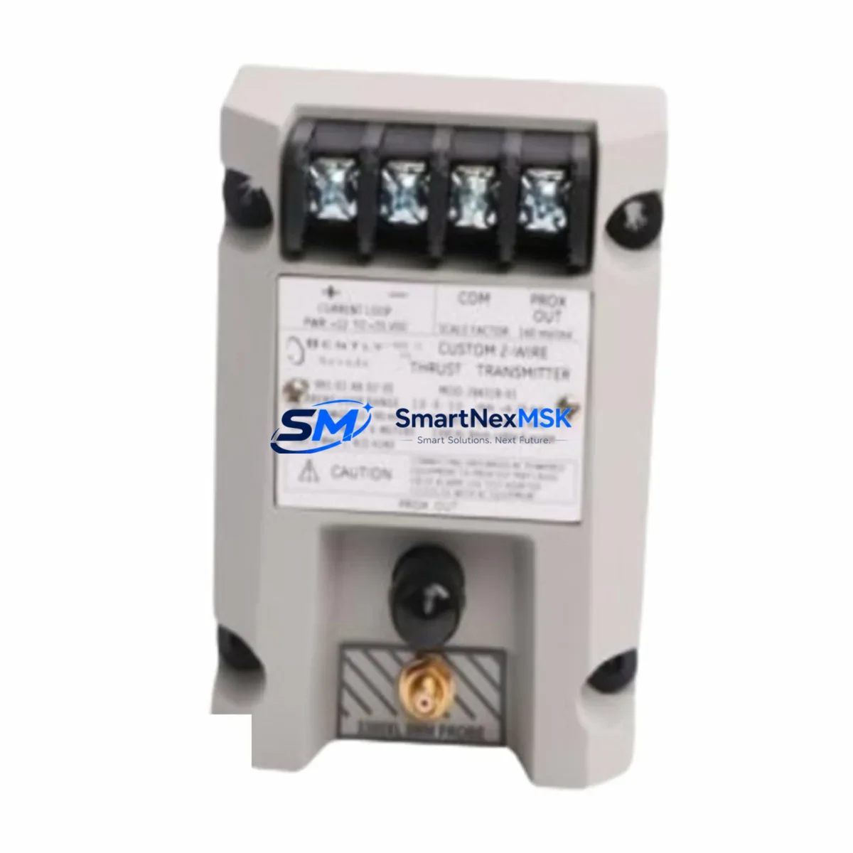
| Output Signal | 4–20 mA analog (standard industrial loop) |
| Compatibility | Bently Nevada 3300, 3500 Series monitoring racks; Proximitor sensor systems |
| Installation | DIN rail / rack-mount per OEM specification |
| Operating Environment | Industrial control room / machinery protection panel |
| Origin | USA (Original OEM) |
| Condition | Original spare — tested and inspected before shipment |
| Warranty | 12 Months |
| Lead Time | In stock — ships within 1–3 business days |
| Maintenance Recommendation | Replace every 5–8 years or upon drift/alarm fault; inspect wiring and Proximitor probe gap annually |
Maintenance Planning for Continuous Operation
When a thrust position fault or transmitter alarm is triggered in a Bently Nevada Proximitor Monitor system, the 991-06-70-01-00 is rarely the only component that requires attention. Experienced maintenance engineers know that a thorough fault isolation process must extend beyond the transmitter itself to the full signal chain and associated control infrastructure.
During planned inspection or emergency replacement of the 991-06-70-01-00, maintenance teams should simultaneously verify the condition of the Proximitor sensor probe (typically an 3300 XL 8mm or 5mm eddy-current probe) and the associated extension cable — both are subject to mechanical wear, connector corrosion, and impedance drift that can mimic transmitter faults. The Proximitor signal conditioner mounted in the rack should also be checked for output voltage stability and calibration drift.
At the rack level, inspect the Bently Nevada 3500/15 Power Supply module supplying the monitoring rack — a degraded power rail can cause erratic transmitter readings and false alarms. The 3500/22M Transient Data Interface or equivalent communication module should be verified for firmware integrity and network connectivity if the system feeds into a plant DCS or historian. If the plant uses a 3500/42M Proximitor/Seismic Monitor card, confirm that the channel configuration and alarm setpoints remain consistent after module replacement.
For facilities running integrated machinery protection, the replacement workflow should also include a check of the 4–20 mA signal isolator feeding the DCS analog input card — signal isolators degrade over time and can introduce offset errors that are incorrectly attributed to the transmitter. Verify the terminal block wiring and shield grounding at both the field junction box and the control cabinet marshalling panel. Loose or corroded terminals are a leading cause of intermittent thrust alarms in aging installations.
If the machinery protection system interfaces with a Bently Nevada 3500/92 Communication Gateway or a Modbus/PROFIBUS adapter, confirm that the gateway configuration is not disrupted during the module swap. Finally, review the overspeed protection relay and any hardwired trip logic connected to the thrust channel to ensure the replacement does not inadvertently alter trip setpoints or bypass protection during commissioning.
Stocking the 991-06-70-01-00 alongside these complementary components — Proximitor probes, extension cables, power supply modules, signal isolators, and communication cards — forms the foundation of a robust critical spare parts strategy for Bently Nevada-based machinery protection systems.
Site Replacement Workflow
Step 1 — Pre-replacement verification: Confirm the fault is isolated to the 991-06-70-01-00 by checking the Proximitor probe gap voltage at the field terminal. A reading outside the –2 VDC to –18 VDC linear range indicates a probe or cable issue rather than a transmitter fault.
Step 2 — Safe isolation: Place the affected channel in bypass mode via the 3500 rack keyswitch or software inhibit before removing the module. This prevents a spurious trip during the swap and maintains machinery protection on remaining channels.
Step 3 — Module removal and inspection: Remove the 991-06-70-01-00 from the rack. Inspect the backplane connector for bent pins, corrosion, or contamination. Clean with contact cleaner if required before installing the replacement unit.
Step 4 — Installation and configuration: Insert the replacement 991-06-70-01-00 and restore rack power. Verify that the channel configuration (gap voltage, scale factor, alarm setpoints) is correctly loaded — use the System 1 software or rack front-panel display to confirm. No hardware jumper changes are typically required for a direct replacement.
Step 5 — Functional test: Apply a known probe gap simulation or use the rack’s built-in self-test to verify the transmitter output tracks correctly across the measurement range. Confirm 4–20 mA output at the DCS analog input card before releasing the channel from bypass.
Step 6 — Documentation: Record the replacement in the equipment maintenance log, update the spare parts inventory, and note the as-found probe gap reading for trend analysis. This data supports future predictive maintenance decisions and extends the operational life of aging Proximitor systems.
Spare Parts Support FAQ
Q1: Is the 991-06-70-01-00 a direct drop-in replacement for the original Bently Nevada unit?
Yes. This is an original OEM spare part — not a third-party replica or remanufactured substitute. It is fully compatible with Bently Nevada 3300 and 3500 Series monitoring racks and requires no hardware modification or reconfiguration beyond standard channel verification after installation.
Q2: What does the 12-month warranty cover?
The 12-month warranty covers manufacturing defects and functional failures under normal operating conditions. Each unit undergoes functional testing and inspection prior to shipment. In the event of a warranty claim, we provide replacement or repair support with priority handling to minimize your downtime exposure.
Q3: How do I verify compatibility before ordering?
Provide your rack model number (e.g., 3500/42M, 3300 Series), the existing module part number from the rack label or system documentation, and your Proximitor probe model. Our technical team will confirm compatibility and advise on any configuration considerations before shipment.
Q4: What is your recommended inventory strategy for critical Bently Nevada spares?
For facilities with continuous-duty rotating machinery, we recommend maintaining at least one 991-06-70-01-00 on-site as a cold spare, alongside matched Proximitor probes and extension cables. For multi-train installations or remote sites with long logistics lead times, a two-unit buffer is advisable. We support long-term supply agreements and can reserve stock against your annual maintenance schedule.
© 2026 SMARTNEXMSK. All rights reserved.
Original Source: https://smartnexmsk.com
Contact: sales@smartnexmsk.com | +86 18259474341


