Bently Nevada CB2W100-125 Retrofit-Ready Interconnect Cable for 3500 Series Control Systems
The Bently Nevada CB2W100-125 is a precision-engineered interconnect cable designed for seamless integration into the Bently Nevada 3500 Series machinery protection and condition monitoring platform. As legacy 3500 Series installations age and original OEM cables reach end-of-life, the CB2W100-125 serves as a verified drop-in replacement that restores full signal integrity between transducer inputs and monitoring rack modules — without requiring firmware changes, rack reconfiguration, or HMI screen remapping.
Industrial facilities operating rotating machinery — including turbines, compressors, pumps, and gearboxes — rely on the 3500 Series for continuous vibration, position, and speed monitoring. When an interconnect cable fails or degrades, the entire monitoring chain is compromised. The CB2W100-125 eliminates unplanned downtime by providing a ready-to-install replacement that matches the original pinout, shielding specification, and connector interface of the factory cable.
Upgrade Compatibility Table
| Parameter | CB2W100-125 Specification | Retrofit Notes |
|---|---|---|
| Compatible Platform | Bently Nevada 3500 Series | Verified for 3500/22M, 3500/42M, 3500/45, 3500/50, 3500/60, 3500/72M |
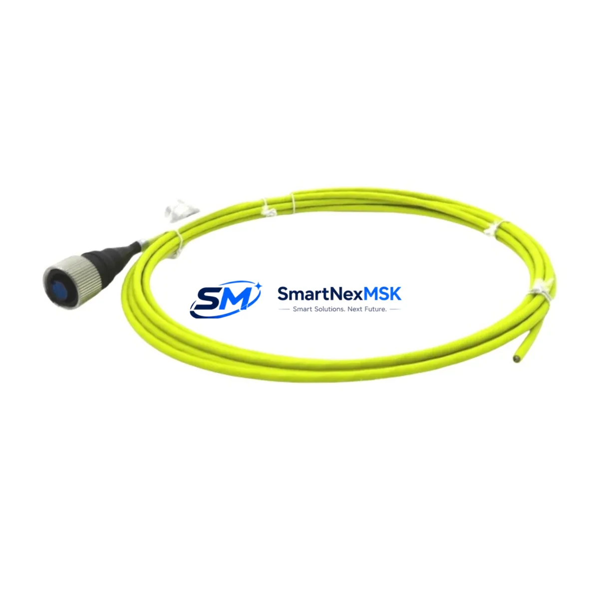
| Cable Length | 100 ft (approx. 30.5 m) | Confirm routing path before installation; avoid sharp bends near connectors |
| Connector Interface | OEM-matched, shielded | Direct plug-in replacement; no adapter required |
| Signal Compatibility | Vibration / Proximity / Speed | Supports eddy-current transducer signal types used with 3500/25 keyphasor modules |
| Installation Requirement | No rack modification needed | Retain existing terminal block wiring on I/O module side |
| Communication Compatibility | Passive signal cable — protocol-agnostic | Compatible with Modbus, Ethernet/IP, and proprietary 3500 backplane communication |
| Replacement Recommendation | Direct OEM equivalent | Replaces degraded, cracked, or shielding-compromised original cables |
| Commissioning Focus | Signal continuity and shield grounding | Verify with loop check before rack power-up; confirm no ground loops |
| Warranty | 12 Months | Covers manufacturing defects; includes pre-shipment continuity test |
Retrofit Planning for Existing Automation Systems
A successful 3500 Series cable retrofit begins well before the maintenance window opens. Engineers should first audit the existing cable routing from the field transducer — typically a Bently Nevada 3300 XL 8mm or 11mm proximity probe — through the junction box and into the 3500 rack. The CB2W100-125 is designed to interface directly with the 3500/20 rack power supply module environment, meaning no additional power conditioning is required at the cable level.
When planning the replacement, confirm that the 3500/42M four-channel general purpose monitor or the 3500/45 position monitor in the target rack slot is configured for the correct transducer type. The module’s internal jumper settings and software configuration — managed via the Bently Nevada System 1 software — must match the transducer sensitivity (typically 7.87 V/mm or 200 mV/mil) before the new cable is energized.
For installations where the 3500 rack communicates upstream via a 3500/92 communication gateway module to a DCS or SCADA platform, the cable swap is transparent to the communication layer. No changes to Modbus register maps or OPC-DA tag configurations are required. However, if the facility is simultaneously migrating from the legacy 3300 Series to the 3500 platform, engineers should also plan for 3500/22M transient data interface module installation and verify that the Bently Nevada TDXnet or equivalent data acquisition path is updated accordingly.
Facilities running parallel I/O expansion should note that the CB2W100-125 is compatible with standard 3500 Series I/O module terminal blocks. If the control cabinet also houses a 3500/60 temperature monitor or 3500/50 tachometer, those modules share the same backplane and power bus — confirming that the rack’s total power budget (typically supplied by a redundant 3500/20 power supply pair) accommodates all active modules before adding or replacing cables is essential.
For sites where the 3500 rack interfaces with a GE Speedtronic Mark VI or Emerson Ovation DCS via hardwired I/O, the cable replacement should be coordinated with the DCS I/O card team to ensure that analog input channels remain in the correct range during the transition. Pre-staging the CB2W100-125 on a bench with a signal simulator before field installation significantly reduces commissioning time.
Downtime Control During System Migration
Minimizing downtime during a 3500 Series cable replacement requires a structured hot-swap protocol. Where the rack supports redundant monitoring paths — such as dual-channel configurations on the 3500/42M — one channel can remain active while the other is disconnected for cable replacement, preserving alarm and trip functionality throughout the procedure.
Before disconnecting the CB2W100-125’s predecessor, technicians should capture a full snapshot of the current system configuration using Bently Nevada System 1 software, including all alarm setpoints, danger thresholds, and OK relay states. This snapshot serves as the baseline for post-installation verification. The original program logic stored in the monitor modules is non-volatile and is not affected by cable removal — there is no risk of configuration loss during the physical swap.
HMI screens connected to the 3500 rack via the 3500/92 gateway will display a transducer not OK (TNK) condition during the cable disconnection interval. Operators should be briefed in advance and the relevant alarm should be placed in bypass mode using the rack’s front-panel keyswitch or via System 1 software to prevent nuisance trips. Once the CB2W100-125 is installed and the loop check confirms correct signal levels, the bypass is removed and the system returns to normal monitoring state.
For critical machinery where any monitoring gap is unacceptable, a portable Bently Nevada SCOUT 100 or equivalent handheld vibration analyzer can be deployed to maintain continuous transducer readings at the field junction box while the rack-side cable is being replaced. This approach ensures that machinery protection is never fully interrupted, even during the brief disconnection window.
Retrofit Support FAQ
Q1: Is the CB2W100-125 a direct replacement for the original Bently Nevada cable, or are adapter connectors required?
The CB2W100-125 is engineered as a direct OEM-equivalent replacement. The connector pinout, shielding configuration, and cable jacket specification match the original factory cable. No adapters, pigtails, or terminal modifications are required for standard 3500 Series rack installations.
Q2: How is the cable tested before shipment?
Each CB2W100-125 unit undergoes a pre-shipment continuity and insulation resistance test. Shield continuity, conductor-to-conductor isolation, and end-to-end signal path integrity are verified. A test record is available upon request. The cable is covered by a 12-month warranty against manufacturing defects from the date of shipment.
Q3: What should be checked during commissioning after installing the CB2W100-125?
After installation, perform a full loop check: apply a known signal at the transducer end and verify the correct reading at the 3500 monitor module. Confirm shield grounding at one end only to prevent ground loops. Check that the OK relay on the target monitor module (e.g., 3500/42M or 3500/45) returns to the OK state and that System 1 software shows the channel as healthy before removing any alarm bypasses.
Q4: Can this cable be used in a mixed 3300/3500 Series rack environment during a phased migration?
The CB2W100-125 is designed for the 3500 Series platform. In phased migration scenarios where 3300 Series modules are still present in adjacent rack slots, the cable can be installed on the 3500 side without interference. However, signal routing from 3300 Series transducer inputs should remain on 3300-compatible cabling until those modules are fully decommissioned and replaced with their 3500 equivalents.
© 2026 SMARTNEXMSK. All rights reserved.
Original Source: https://smartnexmsk.com
Contact: sales@smartnexmsk.com | +86 18259474341


