Bently Nevada TACH100-01 Maintenance-Ready Spare for 3500 Automation
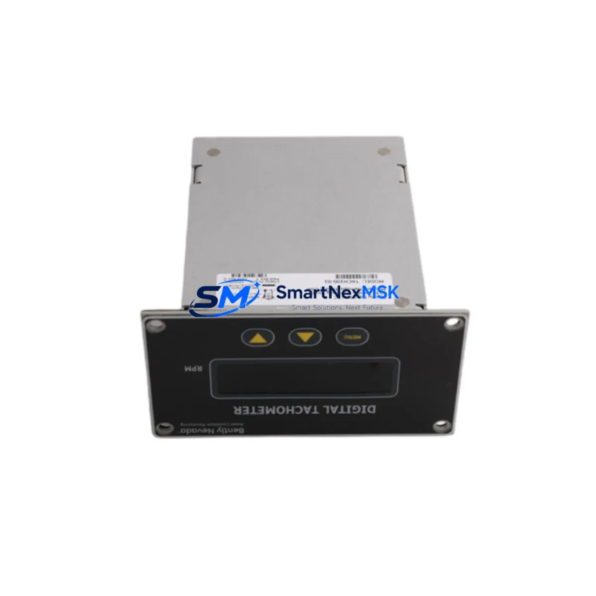
The Bently Nevada TACH100-01 (Part No. 174652-01) is an original single-channel digital tachometer input module designed for the Bently Nevada 3500 Series machinery protection rack system. For maintenance engineers managing rotating equipment — turbines, compressors, pumps, and gearboxes — this module is a critical component in continuous speed and phase monitoring. When this module fails or degrades, the entire protection channel is compromised, creating unacceptable downtime risk in process-critical environments.
At SMARTNEXMSK, every TACH100-01 unit is sourced as an original Bently Nevada spare, individually inspected, function-tested against 3500 rack communication protocols, and shipped with a 12-month warranty. We maintain ready stock to support emergency replacement, planned turnaround maintenance, and long-term spare parts inventory programs for industrial facilities worldwide.
Spare Maintenance Table
| Parameter | Specification |
|---|---|
| Part Number | TACH100-01 / 174652-01 |
| Brand | Bently Nevada |
| Series | 3500 Machinery Protection System |
| Module Type | Single-Channel Digital Tachometer Input Module |
| Input Signal | Digital pulse (proximity probe or magnetic pickup compatible) |
| Speed Range | 1 – 99,999 RPM (configurable) |
| Power Supply | Supplied via 3500 rack backplane (no external PSU required) |
| Communication | 3500 rack internal bus; compatible with 3500/22M Communication Gateway |
| Rack Compatibility | Bently Nevada 3500/05 and 3500/05E Rack Interface Modules |
| Mounting | Standard 3500 Series rack slot (DIN-rail rack chassis) |
| Operating Temperature | 0°C to +65°C |
| Humidity | 5% to 95% RH, non-condensing |
| Condition | Original spare, function-tested before shipment |
| Warranty | 12 Months from date of shipment |
| Lead Time | In stock — ships within 1–3 business days |
| Origin | USA |
Maintenance Planning for Continuous Operation
When a TACH100-01 replacement is scheduled or triggered by a fault alarm, a thorough maintenance engineer will not stop at swapping the tachometer module alone. The 3500 Series rack is an integrated protection system, and adjacent components must be inspected simultaneously to prevent repeat failures and ensure the protection channel is fully restored.
Begin by verifying the 3500/15 Power Supply Module — backplane voltage irregularities are a leading cause of premature tachometer module failure. Inspect the 3500/05 Rack Interface Module for firmware version compatibility with the replacement TACH100-01 unit, particularly if the rack has been in service for more than five years. Check the 3500/22M Communication Gateway Module to confirm that Modbus or Ethernet/IP communication to the DCS or SCADA layer is intact after module swap.
On the field wiring side, inspect the proximity probe extension cables (typically Bently Nevada 330130 or 330180 series) for insulation degradation, connector corrosion, and continuity. A degraded cable will produce erratic speed signals even with a new tachometer module installed. Verify the Keyphasor® transducer gap voltage and signal amplitude — the TACH100-01 relies on a clean Keyphasor reference for phase angle calculations, and a drifting transducer will cause false trip conditions.
For facilities running parallel vibration monitoring, also inspect the 3500/42M Proximitor®/Seismic Monitor Module and the 3500/40M Proximitor® Monitor in adjacent rack slots. These modules share the same backplane power rail and communication bus, and a failing tachometer module can sometimes mask underlying issues in vibration channels. If the rack includes a 3500/32 4-Channel Relay Module, verify relay output wiring and setpoint configuration after the tachometer replacement to ensure trip logic is correctly restored.
For facilities with older 3300 Series or 7200 Series legacy systems being migrated to 3500 architecture, SMARTNEXMSK also maintains stock of compatible signal conditioners and I/O terminal blocks to support hybrid rack configurations during phased upgrades. Maintaining a minimum of one spare TACH100-01 per critical machine train is standard practice in ISO 55000-aligned asset management programs.
Site Replacement Workflow
Step 1 — Pre-Replacement Verification: Before removing the existing module, document the current speed reading, alarm setpoints, and Keyphasor configuration via the 3500 Rack Configuration Software (RCS). Export the rack configuration file as a backup. Confirm the replacement TACH100-01 part number (174652-01) matches the installed module label exactly.
Step 2 — Safe Isolation: Coordinate with the control room to place the affected protection channel in bypass mode. Do not power down the entire rack unless required — the 3500 system supports hot-swap of individual modules in most configurations. Verify bypass status on the 3500/05 Rack Interface Module front panel LEDs before proceeding.
Step 3 — Module Removal and Installation: Disconnect field wiring at the I/O terminal block. Remove the faulty TACH100-01 by releasing the front-panel locking mechanism. Insert the replacement module firmly until the backplane connector is fully seated. Reconnect field wiring per the original termination drawing, verifying polarity and shield grounding.
Step 4 — Configuration Restore and Functional Test: Upload the saved rack configuration file via RCS. Verify that the module self-test passes (green STATUS LED). Confirm speed reading matches the reference tachometer or DCS historian value within ±1 RPM. Check alarm and trip setpoints are correctly restored. Remove bypass and return the protection channel to active monitoring.
Step 5 — Documentation: Record the replacement in the plant CMMS (e.g., SAP PM or Maximo), including the new module serial number, installation date, and post-replacement test results. Update the spare parts inventory to trigger reorder of a replacement TACH100-01 unit to maintain minimum stock levels.
Spare Parts Support FAQ
Q1: Is the TACH100-01 (174652-01) compatible with all 3500 Series rack configurations?
The TACH100-01 is designed for standard 3500 Series racks using the 3500/05 or 3500/05E Rack Interface Module. Compatibility with specific rack firmware versions should be verified via the Bently Nevada 3500 System Configuration Guide. SMARTNEXMSK can provide technical documentation to support compatibility verification prior to purchase.
Q2: What testing is performed before shipment?
Every TACH100-01 unit undergoes functional testing including power-on self-test verification, backplane communication check, and signal input/output validation before shipment. Units that do not pass all test criteria are not shipped. A test report is available upon request.
Q3: What does the 12-month warranty cover?
The 12-month warranty covers manufacturing defects and functional failures under normal operating conditions as specified in the Bently Nevada 3500 Series documentation. It does not cover damage resulting from incorrect installation, overvoltage, or use outside the specified environmental range. Warranty claims are processed with full technical support from SMARTNEXMSK.
Q4: Can SMARTNEXMSK support long-term spare parts supply for the 3500 Series?
Yes. SMARTNEXMSK maintains ongoing stock of 3500 Series modules including tachometer, vibration monitor, relay, power supply, and communication modules to support both emergency replacement and planned annual maintenance programs. Long-term supply agreements and consignment stock arrangements are available for facilities with high-criticality rotating equipment fleets.
© 2026 SMARTNEXMSK. All rights reserved.
Original Source: https://smartnexmsk.com
Contact: sales@smartnexmsk.com | +86 18259474341


