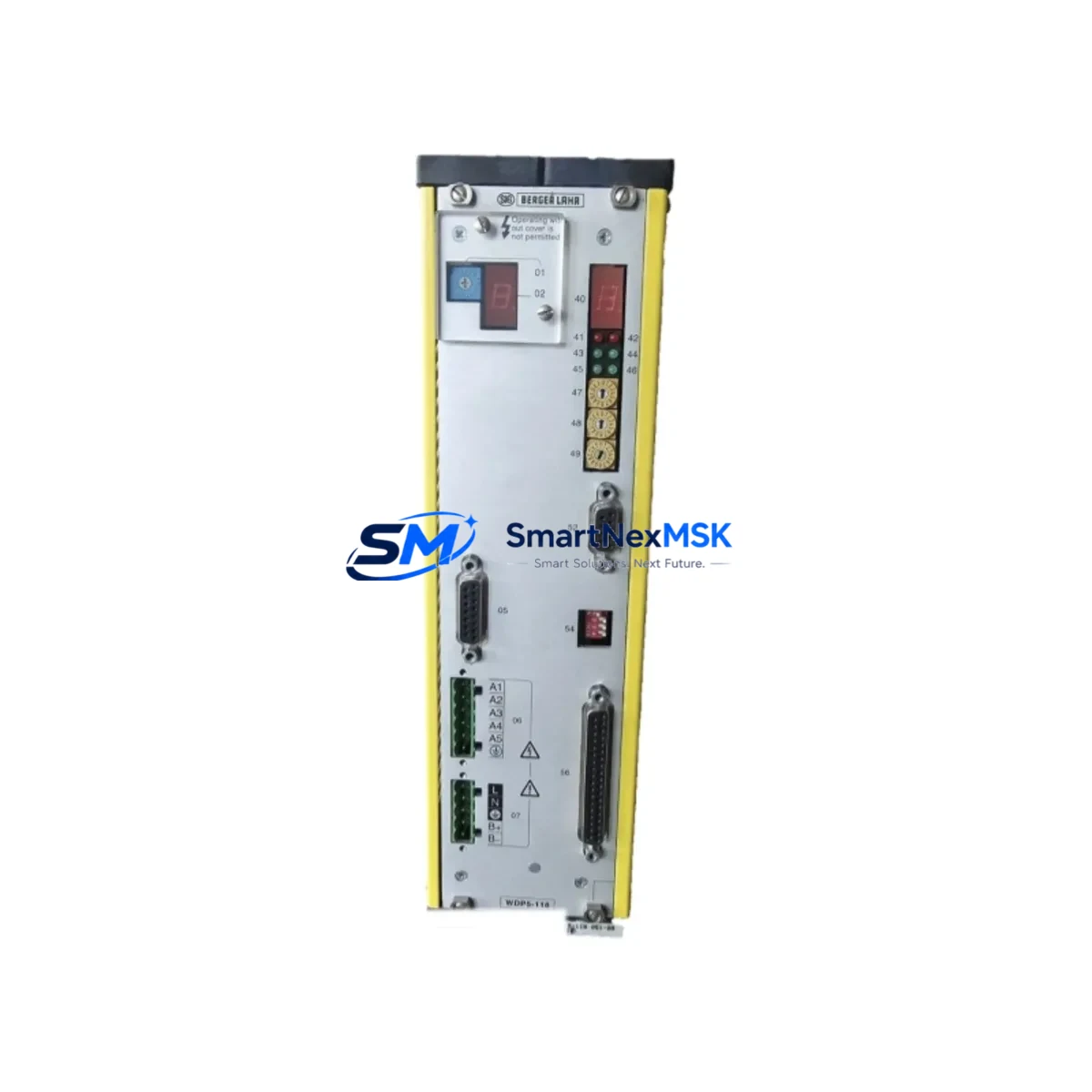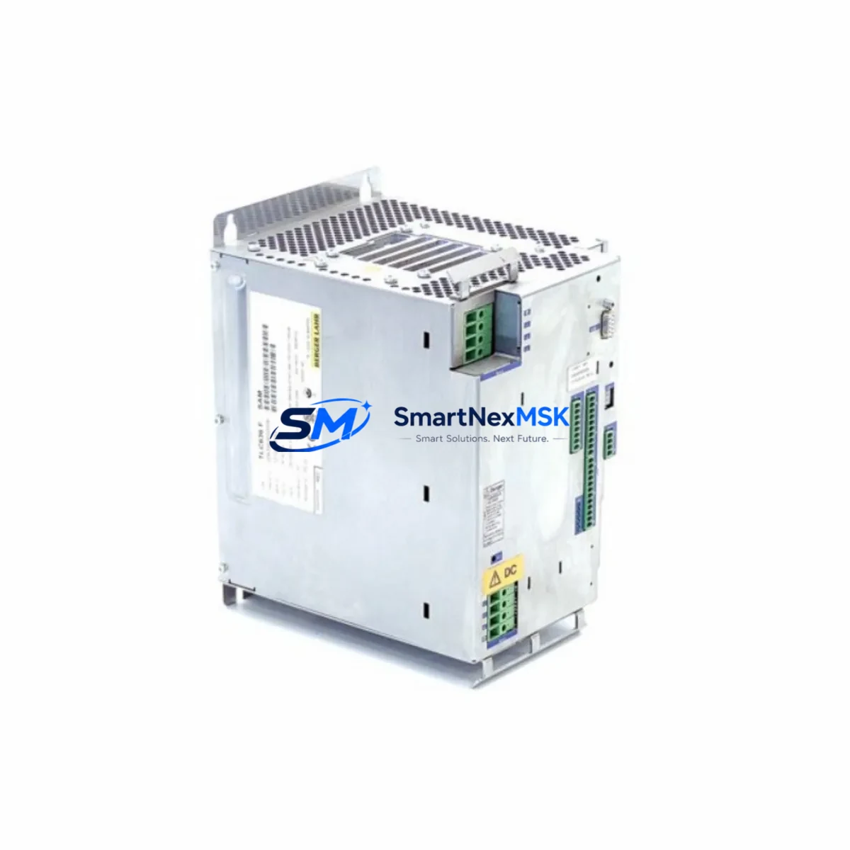
BERGER LAHR TLC511 F Spare for TLC511 Series Automation: Spare Replacement & Industrial Downtime Risk Control
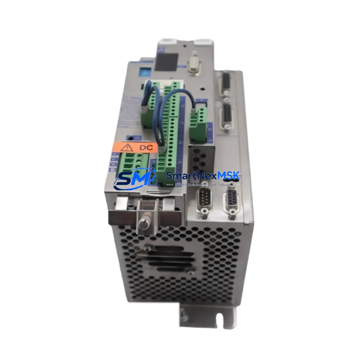
The BERGER LAHR TLC511 F is an original AC servo drive spare part designed for the TLC511 Series motion control platform. In industrial automation environments — from packaging lines and CNC machining centers to material handling conveyors and press control systems — an unplanned servo drive failure can halt production within seconds. Sourcing a verified, tested replacement unit is the fastest path to restoring operation and protecting your maintenance KPIs.
This unit is supplied as an original BERGER LAHR component, inspected and function-tested prior to shipment. It is backed by a 12-month warranty covering manufacturing defects and operational failures under normal industrial use conditions. Fast worldwide dispatch ensures your maintenance team receives the part with minimal lead time, reducing mean time to repair (MTTR) on critical motion axes.
Whether you are managing a planned overhaul, responding to an emergency fault, or building a strategic spare parts buffer for aging TLC511-based systems, the TLC511 F is a direct-fit replacement that preserves your existing wiring, parameter configuration, and mechanical mounting without system redesign.
Spare Maintenance Table
| Parameter | Specification / Detail |
|---|---|
| SKU / Part Number | TLC511 F |
| Brand | BERGER LAHR |
| Series | TLC511 |
| Product Type | AC Servo Drive |
| Application | Motion control, servo axis positioning, CNC, packaging, press automation |
| Compatibility | TLC511 Series servo systems; compatible with BERGER LAHR servo motors and TLC-family controllers |
| Origin | Germany (DE) |
| Weight | 2,260 g |
| Mounting | DIN rail / panel mount (standard TLC511 Series footprint) |
| Installation Environment | Industrial control cabinet; IP20 internal enclosure |
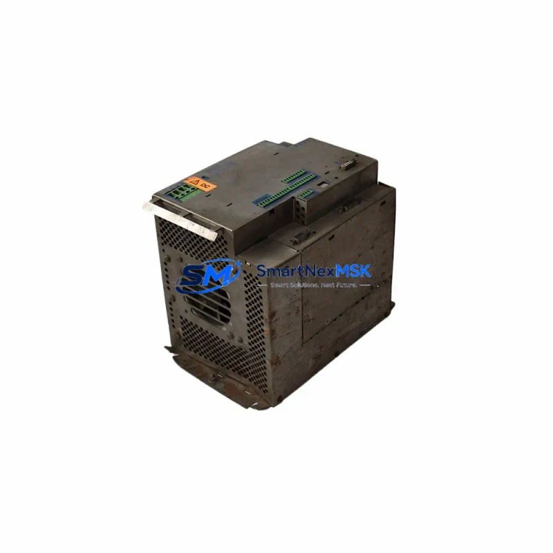
| Condition | Original spare — inspected and function-tested before shipment |
| Warranty | 12 months from date of shipment |
| Shipping | Worldwide express; ESD-safe packaging |
Maintenance Planning for Continuous Operation
When replacing the TLC511 F in a live control cabinet, a disciplined maintenance engineer will not stop at the servo drive alone. The TLC511 Series drive operates within an interconnected electrical system, and adjacent components are often subject to the same thermal cycling, voltage transients, and service hours that caused the original failure.
During the same maintenance window, inspect and consider stocking the following related components:
- BERGER LAHR servo motor feedback cables and encoder connectors — signal degradation on the feedback line is a common root cause of TLC511 F faults; replace if insulation shows cracking or connector pins show oxidation.
- 24 VDC control power supply module — the logic supply feeding the TLC511 F control board should be verified for output ripple and voltage stability; a failing SMPS can cause intermittent drive faults that mimic encoder errors.
- Braking resistor unit — if the application involves frequent deceleration cycles (e.g., press or hoist), the external braking resistor should be checked for resistance drift and thermal damage.
- TLC511 Series communication module or fieldbus adapter — PROFIBUS DP or CANopen interface cards fitted to the drive should be inspected for firmware compatibility after a drive swap.
- I/O terminal block and wiring harness — inspect the 24 V digital I/O terminals for loose crimps, corroded ferrules, and overheated insulation, particularly on enable, fault reset, and speed reference inputs.
- Contactor and motor protection relay — the main power contactor upstream of the drive and the motor thermistor relay should be tested for contact wear and correct trip thresholds.
- EMC line filter — the mains-side EMC filter should be checked for capacitor leakage and correct grounding; a degraded filter can introduce noise that triggers nuisance drive trips after replacement.
- Fuse holders and semiconductor fuses — replace any fast-acting semiconductor fuses in the DC bus circuit as a precaution, especially if the original failure involved an overcurrent event.
- HMI operator panel or parameter backup device — before powering down, back up the drive parameters via the HMI or a handheld programmer to ensure the replacement unit can be configured to the exact same axis settings.
- Signal isolator or analog input conditioner — if the speed or torque reference is provided via a 0–10 V or 4–20 mA analog signal, verify the signal isolator output accuracy and replace if drift exceeds ±0.5%.
Stocking these components alongside the TLC511 F in your spare parts cabinet significantly reduces the risk of a second unplanned stoppage caused by a secondary failure discovered only after the drive has been replaced and the system re-energized.
Site Replacement Workflow
Step 1 — Fault Isolation: Record all active fault codes from the TLC511 F display or via the connected HMI before de-energizing. Photograph the wiring layout and terminal assignments for reference during reinstallation.
Step 2 — Safe De-energization: Isolate the main power supply and the 24 VDC control supply. Wait for the DC bus capacitors to discharge fully (minimum 5 minutes after power-off, or confirm with a DC voltmeter).
Step 3 — Mechanical Removal: Disconnect the motor power cable (U/V/W), the encoder/resolver feedback cable, the control I/O connector, and the fieldbus interface. Remove the drive from the DIN rail or panel mounting using the standard TLC511 Series release mechanism.
Step 4 — Replacement Unit Installation: Mount the new TLC511 F in the same position. Reconnect all cables in the reverse order of removal. Verify cable shielding and grounding connections are intact.
Step 5 — Parameter Restore: Upload the saved parameter set to the replacement drive via the HMI or programming tool. Verify motor data, axis limits, ramp times, and fieldbus node address match the original configuration.
Step 6 — Commissioning Check: Perform a low-speed jog test before returning the axis to full production speed. Monitor drive temperature, current draw, and feedback signal quality during the first 30 minutes of operation.
This workflow minimizes downtime, preserves system compatibility, and ensures the replacement TLC511 F is operating within its specified parameters before full production load is applied.
Spare Parts Support FAQ
Q1: Is the TLC511 F a direct drop-in replacement for my existing BERGER LAHR TLC511 Series drive?
Yes. The TLC511 F is an original BERGER LAHR spare part manufactured to the same specification as the series-production unit. It uses the same mechanical footprint, connector pinout, and parameter structure, allowing direct substitution without hardware modification. Confirm your existing firmware version and motor data set before powering up to ensure full compatibility.
Q2: How is the unit tested before shipment?
Each TLC511 F unit undergoes a pre-shipment functional inspection covering power-on self-test, DC bus integrity, control board communication, and output stage verification. Units that do not pass inspection are not dispatched. The 12-month warranty covers failures arising from manufacturing defects or component faults under normal operating conditions.
Q3: What is the recommended spare parts stocking strategy for TLC511-based systems?
For systems with three or more TLC511 axes, we recommend holding at least one TLC511 F drive in local stock at all times. For critical single-axis applications (e.g., main press drive or primary conveyor), consider a dedicated hot-spare unit. Pair the drive spare with a set of feedback cables, a braking resistor, and a 24 VDC power supply module to cover the most common failure modes in a single maintenance response.
Q4: Can you support long-term supply for legacy TLC511 systems that are no longer in production?
Yes. We specialize in long-term spare parts supply for discontinued and end-of-life industrial automation components. The TLC511 F is available from our managed inventory, and we can discuss scheduled supply agreements to support your planned maintenance calendar and system life extension programs beyond the original OEM support window.
© 2026 SMARTNEXMSK. All rights reserved.
Original Source: https://smartnexmsk.com
Contact: sales@smartnexmsk.com | +86 18259474341