Bombardier 3EST000212-0728 Maintenance-Ready Spare for 3EST Automation
The Bombardier 3EST000212-0728 is an original DCS I/O interface module designed for continuous-duty industrial automation environments. As a critical spare part in 3EST-series distributed control systems, this module supports maintenance engineers and procurement teams in executing rapid fault isolation, planned overhaul cycles, and emergency replacement without extended production downtime. Whether you are managing a scheduled shutdown or responding to an unplanned trip, having a verified, tested 3EST000212-0728 in your spare parts inventory is a fundamental risk-control measure for any facility running Bombardier DCS infrastructure.
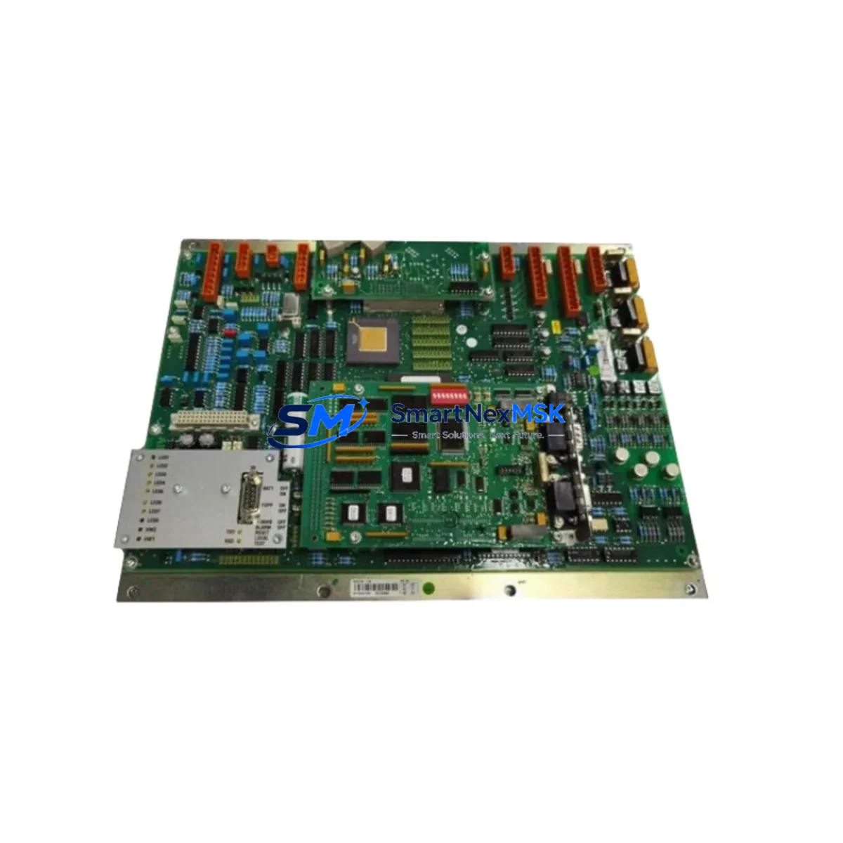
The 3EST000212-0728 serves as a direct interface between field instrumentation and the DCS controller backplane. Its role in signal conditioning, I/O mapping, and channel-level diagnostics makes it one of the most frequently inspected components during control cabinet audits. When this module shows signs of degradation — intermittent channel faults, communication timeouts, or abnormal LED status — immediate replacement is the recommended corrective action to prevent cascade failures across the I/O loop.
From a maintenance planning perspective, the 3EST000212-0728 should be evaluated alongside the broader I/O subsystem. During a planned replacement, engineers are advised to inspect the associated terminal blocks and field wiring for insulation wear, verify the backplane connector pins for oxidation or mechanical damage, and confirm that the module address configuration matches the existing DCS database. Any mismatch in slot addressing or I/O channel mapping will require a corresponding update in the control system configuration before the module is brought online.
Spare Maintenance Table
| Parameter | Specification / Recommendation |
|---|---|
| Part Number | 3EST000212-0728 |
| Brand | Bombardier |
| Series | 3EST DCS I/O Series |
| Module Type | DCS I/O Interface Module |
| Compatibility | 3EST-series DCS backplanes and controller racks |
| Installation | Direct slot insertion; verify backplane connector alignment before seating |
| Communication | Compatible with 3EST DCS internal bus protocol |
| Replacement Scope | Drop-in replacement for original 3EST000212-0728; confirm firmware revision if applicable |
| Commissioning Note | Verify I/O channel mapping, module address, and field wiring continuity post-installation |
| Warranty | 12-Month Warranty — tested before shipment |
Maintenance Planning for Continuous Operation
Effective spare parts management for a Bombardier 3EST DCS installation requires a systems-level approach. The 3EST000212-0728 does not operate in isolation — its performance depends on the integrity of the surrounding electrical and control infrastructure. When planning a replacement or conducting a control cabinet inspection, maintenance engineers should simultaneously assess the condition of the 3EST series power supply module, which provides regulated DC voltage to the I/O rack. A degraded power supply can cause intermittent module faults that are incorrectly attributed to the I/O card itself.
The backplane or I/O rack chassis should be inspected for mechanical damage, connector wear, and proper grounding. Loose backplane connections are a common source of sporadic communication errors between the 3EST000212-0728 and the DCS controller. Terminal blocks on the field wiring side should be checked for torque compliance and corrosion, particularly in high-humidity or chemically aggressive environments.
Signal isolators installed between field transmitters and the I/O module inputs play an important role in protecting the 3EST000212-0728 from voltage spikes and ground loops. If the module has failed due to an electrical transient, the associated signal isolators should be replaced as part of the same maintenance event. Similarly, fuse holders and miniature circuit breakers protecting the I/O loop circuits should be tested for continuity and correct rating.
For facilities using Bombardier DCS communication modules to link the I/O subsystem to the supervisory network, the communication link integrity should be verified after any I/O module replacement. This includes checking the communication cable connections, verifying network node addresses, and confirming that the DCS historian and HMI screens are receiving updated process values from the replaced module’s channels.
Where the 3EST DCS system interfaces with a SCADA or HMI panel, operators should confirm that all associated HMI faceplates and alarm setpoints are functioning correctly after the replacement. Any I/O channel that was in a forced or bypassed state during the fault condition should be released and verified against the process baseline. Relay output modules connected downstream of the 3EST000212-0728 should also be tested to confirm correct switching behavior under normal operating conditions.
Site Replacement Workflow
The on-site replacement of the Bombardier 3EST000212-0728 follows a structured sequence designed to minimize downtime and protect the integrity of the existing control program. Before removing the faulty module, the maintenance team should document the current I/O channel status, note any active alarms, and place the affected control loops in manual mode at the DCS workstation. This prevents uncontrolled process responses during the module swap.
Power to the affected I/O rack section should be isolated in accordance with the site’s lockout/tagout procedure. The field wiring connections should be labeled and photographed before disconnection to ensure accurate re-termination. The replacement 3EST000212-0728 should be inspected for physical damage and verified against the original part number before installation.
After seating the new module in the backplane slot, power should be restored and the DCS diagnostic display checked for module recognition and channel health status. Each I/O channel should be individually verified against the field instrument reading before the control loops are returned to automatic mode. A post-replacement functional test, including a simulated process signal injection where applicable, is recommended to confirm full channel operability before signing off the maintenance record.
This workflow applies equally to planned maintenance replacements and emergency fault recovery scenarios. Having a pre-tested, in-stock 3EST000212-0728 available reduces the mean time to repair and supports the facility’s overall equipment effectiveness targets. All units supplied by SMARTNEXMSK are tested before shipment and covered by a 12-month warranty, providing procurement engineers with a reliable, documented supply chain for long-term spare parts management.
Spare Parts Support FAQ
Q1: Is the 3EST000212-0728 still in production, and can I source it as a long-term spare?
The 3EST000212-0728 may be at end-of-life or in limited production. SMARTNEXMSK maintains inventory of original and compatible units to support facilities requiring long-term spare parts supply. Contact our team to confirm current stock availability and lead times.
Q2: How do I verify compatibility before installing the replacement module?
Confirm that the replacement unit carries the same part number (3EST000212-0728) and, where applicable, the same firmware or hardware revision as the original. Check the DCS configuration database to ensure the module slot address and I/O channel assignments match. If in doubt, contact SMARTNEXMSK technical support for pre-installation compatibility verification.
Q3: What testing is performed before shipment?
All 3EST000212-0728 units supplied by SMARTNEXMSK undergo functional testing prior to dispatch. Test records are available upon request. Each unit is shipped with a 12-month warranty covering manufacturing defects and functional failures under normal operating conditions.
Q4: What should I do if the replacement module does not resolve the fault?
If the fault persists after installing the replacement 3EST000212-0728, the root cause may lie in the backplane, power supply, field wiring, or upstream communication path. SMARTNEXMSK’s technical team can assist with fault diagnosis and recommend additional spare components to support a complete system recovery.
© 2026 SMARTNEXMSK. All rights reserved.
Original Source: https://smartnexmsk.com
Contact: sales@smartnexmsk.com | +86 18259474341