BOMBARDIER DCC2390A-3EST49-116-DTCC901B Maintenance-Ready Spare for DTCC901B Series Automation
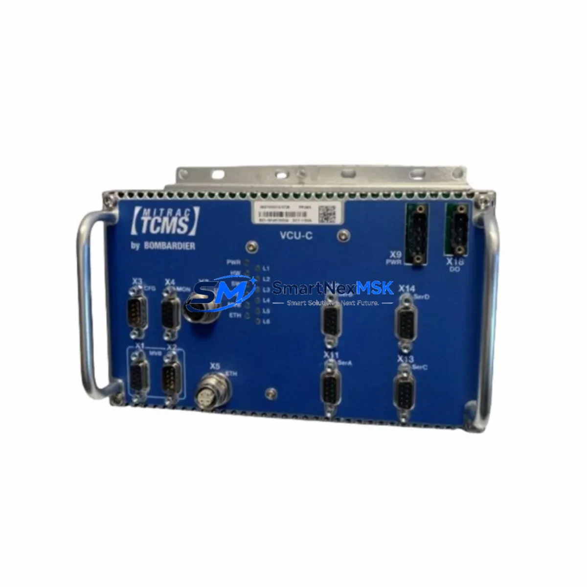
The BOMBARDIER DCC2390A-3EST49-116-DTCC901B is an original drive control unit engineered for DTCC901B series rail traction and industrial automation platforms. As a maintenance-ready spare, this module is sourced, inspected, and dispatched to support rapid fault recovery, planned overhaul cycles, and long-term system continuity. Whether you are managing a scheduled maintenance window or responding to an unplanned shutdown, having a verified replacement unit on hand is the single most effective strategy for minimizing downtime and protecting operational continuity.
Maintenance engineers and procurement specialists working with BOMBARDIER DTCC901B series platforms understand that the drive control unit sits at the heart of traction power management. A failure at this node cascades rapidly into propulsion loss, safety interlock activation, and full system shutdown. Sourcing a tested, original-specification replacement — rather than an unverified substitute — is not merely a preference; it is a maintenance engineering requirement. This unit ships with full functional verification, original labeling, and a 12-month warranty covering defects in materials and workmanship.
Our supply chain for BOMBARDIER spare parts is built around industrial maintenance realities: long lead times from OEM channels, obsolescence risk for legacy DTCC901B hardware, and the operational pressure of keeping aging fleets and automation systems running beyond their original design life. We maintain buffer stock of high-demand BOMBARDIER drive control modules specifically to serve emergency replacement and planned overhaul demand.
Spare Maintenance Table
| Parameter | Specification / Detail |
|---|---|
| Part Number / SKU | DCC2390A-3EST49-116-DTCC901B |
| Brand | BOMBARDIER |
| Series | DTCC901B |
| Product Type | Drive Control Unit |
| Application | Rail Traction Drive Control, Industrial Automation Control Systems |
| Compatibility | DTCC901B Series Traction Control Platforms; BOMBARDIER propulsion and drive control architectures |
| Origin | Canada (BOMBARDIER Transportation) |
| Condition | Original / Surplus / Tested |
| Installation | Direct replacement for existing DCC2390A-3EST49-116-DTCC901B installations; verify connector pinout and firmware revision before commissioning |
| Operating Environment | Industrial rail and automation environments; confirm enclosure IP rating and ambient temperature range with site specifications |
| Maintenance Recommendation | Replace as part of scheduled drive control overhaul; inspect associated power supply rails, I/O wiring harnesses, and communication interfaces at time of replacement |
| Warranty | 12 Months — covers defects in materials and workmanship from date of shipment |
| Lead Time | In-stock units ship within 1–3 business days; contact for volume or expedited requirements |
| Testing | Functionally verified prior to dispatch |
Maintenance Planning for Continuous Operation
When replacing the DCC2390A-3EST49-116-DTCC901B, a disciplined maintenance engineer will not treat the swap as an isolated component exchange. The DTCC901B drive control architecture integrates tightly with upstream power supply modules, downstream I/O expansion cards, and lateral communication interfaces. A fault that has stressed the drive control unit to the point of failure has almost certainly imposed transient overvoltage or overcurrent conditions on adjacent components.
At the time of replacement, the following associated components should be inspected or proactively replaced as part of the same maintenance event:
Power Supply Modules: The 24 VDC and 48 VDC auxiliary power supply modules feeding the DTCC901B control rack should be load-tested and output ripple measured. A degraded power supply is a common root cause of drive control unit failure and will destroy a replacement unit if not addressed. BOMBARDIER-compatible DC/DC converter modules and regulated PSU boards for the DTCC901B rack — such as the DTCC901B-PSU series regulated power supply — should be held as companion spares.
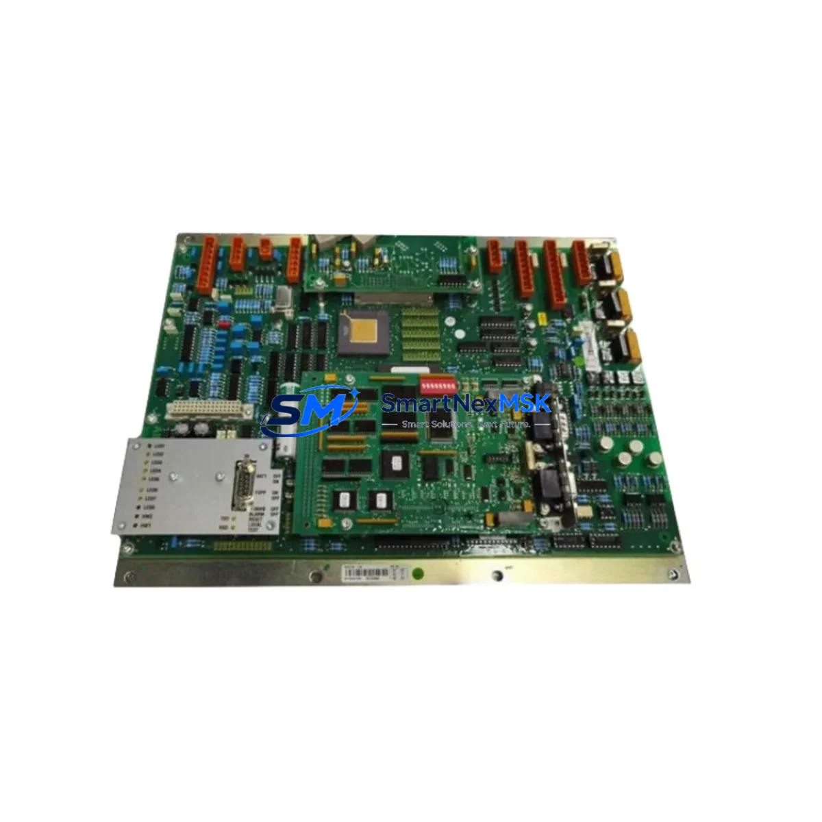
I/O Interface Cards: Digital input and digital output cards connected to the DCC2390A-3EST49-116-DTCC901B should be inspected for burned traces, failed optocouplers, and damaged terminal blocks. BOMBARDIER DTCC901B series I/O modules — including analog input cards for speed and torque feedback and digital output relay interface boards — are high-wear items in traction environments and should be part of any comprehensive spare parts inventory.
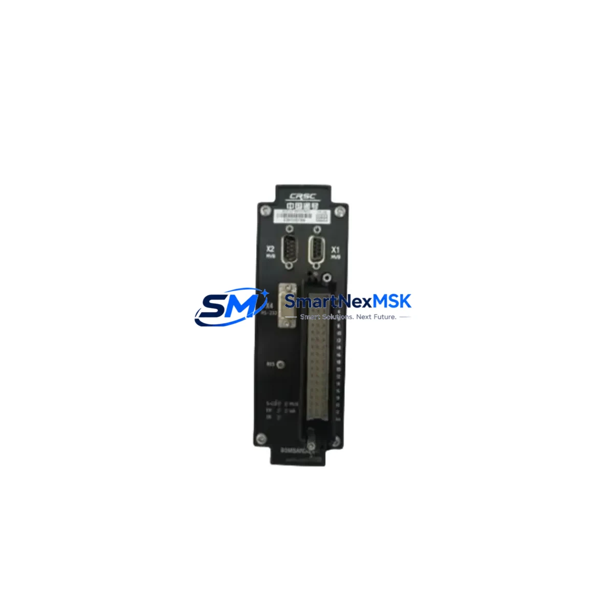
Communication and Network Modules: MVB (Multifunction Vehicle Bus) interface cards, CANopen gateway modules, and Ethernet communication adapters connected to the DTCC901B control node should be verified for signal integrity. A failed or marginal MVB communication module can cause the replacement drive control unit to fault immediately on commissioning, leading to misdiagnosis and unnecessary additional downtime.
Relay and Contactor Assemblies: Output relay modules and power contactors in the traction control cabinet driven by the DCC2390A-3EST49-116-DTCC901B should be inspected for contact wear, coil resistance, and arc erosion. DTCC901B-series relay output modules with high cycle counts should be replaced preventively during the same maintenance window.
Signal Isolation and Protection Components: Signal isolators, surge protection devices (SPDs), and fuse assemblies on the 24 VDC control bus should be checked. Blown fuses or degraded SPDs are frequently overlooked during emergency replacements and are a leading cause of repeat failures. DIN-rail signal isolators and terminal block fuse holders at the drive control unit connector should be inspected for fretting corrosion, loose crimps, and insulation breakdown.
HMI and Operator Interface Panels: If the DTCC901B system includes a local HMI or operator display panel — such as a BOMBARDIER DTCC901B operator interface terminal — verify that the panel firmware is compatible with the replacement drive control unit revision. Firmware mismatches between the HMI and the drive control unit can cause parameter read errors and prevent successful commissioning.
Backplane and Rack Infrastructure: The DTCC901B system backplane and rack mounting hardware should be inspected for bent connector pins, corrosion, and mechanical damage. A damaged backplane connector is a common hidden cause of intermittent drive control faults and should be replaced if any wear is detected.
Maintaining a consolidated spare parts kit — covering the DCC2390A-3EST49-116-DTCC901B alongside its associated power, I/O, communication, relay, signal isolation, and protection components — is the most cost-effective strategy for managing DTCC901B system availability over a multi-year maintenance horizon.
Site Replacement Workflow
The following workflow is designed to minimize total downtime from fault detection to return-to-service, typically achievable within a single maintenance shift when a verified replacement unit is available on-site. It also ensures that the replacement DCC2390A-3EST49-116-DTCC901B is installed correctly and that legacy DTCC901B hardware is retired in a controlled, documented manner.
Step 1 — Fault Isolation: Before removing the DCC2390A-3EST49-116-DTCC901B, document all active fault codes from the DTCC901B system diagnostic interface. Photograph connector positions, cable routing, and any visible damage. This documentation is essential for root cause analysis and warranty claims.
Step 2 — Power Isolation: De-energize the traction control cabinet following site lockout/tagout (LOTO) procedures. Verify zero voltage on all supply rails to the DTCC901B rack before disconnecting the drive control unit. Allow capacitor discharge time as specified in the BOMBARDIER maintenance manual for the DTCC901B series.
Step 3 — Module Removal and Inspection: Remove the faulty DCC2390A-3EST49-116-DTCC901B and inspect the connector pins, backplane contacts, and mounting hardware. Clean the backplane slot and verify that no debris or corrosion is present before installing the replacement unit. This is also the correct moment to inspect the DTCC901B backplane connector assembly and adjacent I/O wiring harnesses for secondary damage.
Step 4 — Replacement Installation: Install the replacement DCC2390A-3EST49-116-DTCC901B, ensuring correct seating on the backplane and secure connector engagement. Verify that the unit’s hardware revision and firmware version are compatible with the DTCC901B system configuration. If a firmware update is required, perform it before energizing the system. Confirm that the 24 VDC auxiliary power supply output is within specification before applying power to the new module.
Step 5 — Commissioning and Verification: Re-energize the system and monitor the DTCC901B diagnostic interface for fault codes. Perform a controlled functional test of the drive control outputs — including relay output verification and I/O channel scan — before returning the system to service. Document the replacement in the maintenance log, including the new unit’s serial number and the date of installation.
This structured approach replaces aging or failed DTCC901B drive control hardware with minimal disruption, maintains full system compatibility, and provides a documented audit trail for maintenance compliance and warranty support.
Spare Parts Support FAQ
Q: What is the warranty coverage for the DCC2390A-3EST49-116-DTCC901B replacement unit?
A: All units ship with a 12-month warranty covering defects in materials and workmanship from the date of shipment. Warranty claims are supported by our technical team and include replacement or repair of confirmed defective units. Units must be installed and operated within their specified environmental and electrical parameters to maintain warranty validity.
Q: How do I verify compatibility between the replacement unit and my existing DTCC901B system?
A: Compatibility is confirmed by matching the full part number — DCC2390A-3EST49-116-DTCC901B — including the suffix, which encodes hardware revision and configuration data. Before ordering, provide your existing unit’s full nameplate data and system configuration details. Our technical team will cross-reference against known DTCC901B system variants to confirm direct replaceability.
Q: What pre-shipment testing is performed on each unit?
A: Each DCC2390A-3EST49-116-DTCC901B unit undergoes functional verification prior to dispatch, including power-on testing, I/O channel verification, and communication interface checks where applicable. Units are packed in anti-static, shock-protected packaging to prevent transit damage. A test report is available upon request for units requiring documented incoming inspection.
Q: Can you support long-term or scheduled spare parts supply for DTCC901B systems?
A: Yes. We support both emergency single-unit orders and long-term supply agreements for DTCC901B series components. For maintenance teams managing fleets or multi-site installations, we offer reserved stock arrangements and priority dispatch agreements. Contact our sales team to discuss volume requirements, lead time commitments, and consolidated spare parts kitting for BOMBARDIER DTCC901B platforms.
© 2026 SMARTNEXMSK. All rights reserved.
Original Source: https://smartnexmsk.com
Contact: sales@smartnexmsk.com | +86 18259474341