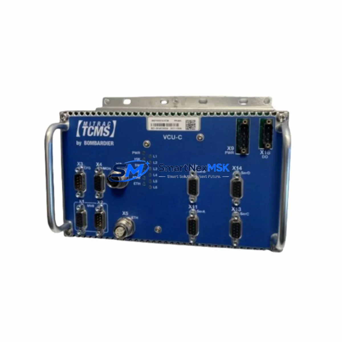
BOMBARDIER 3EST27-99 Retrofit-Ready Transmission Interface for EST Series Control Systems
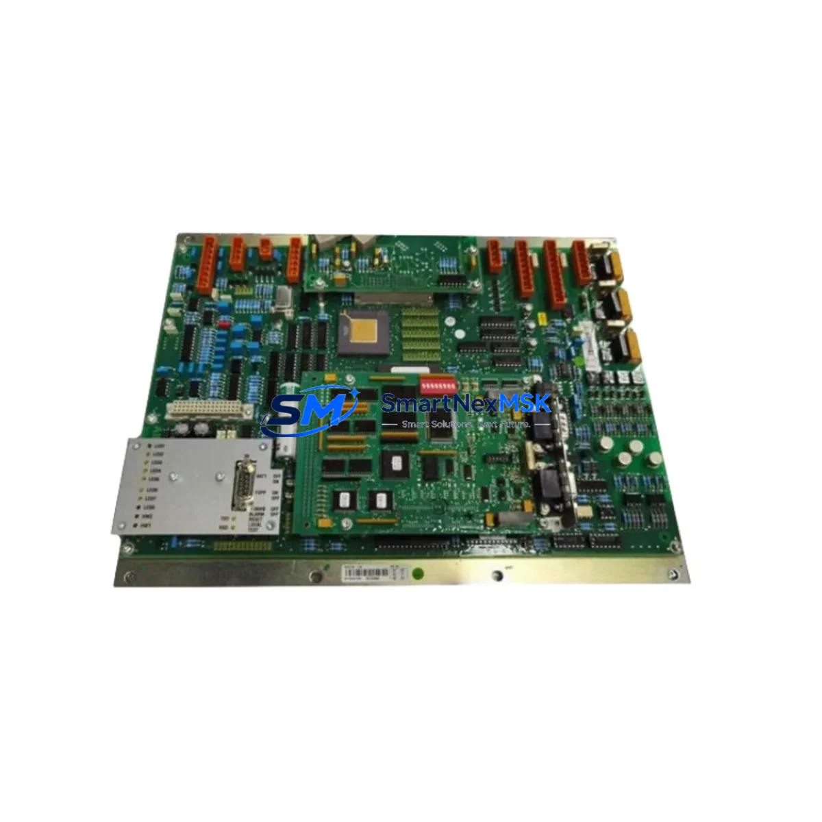
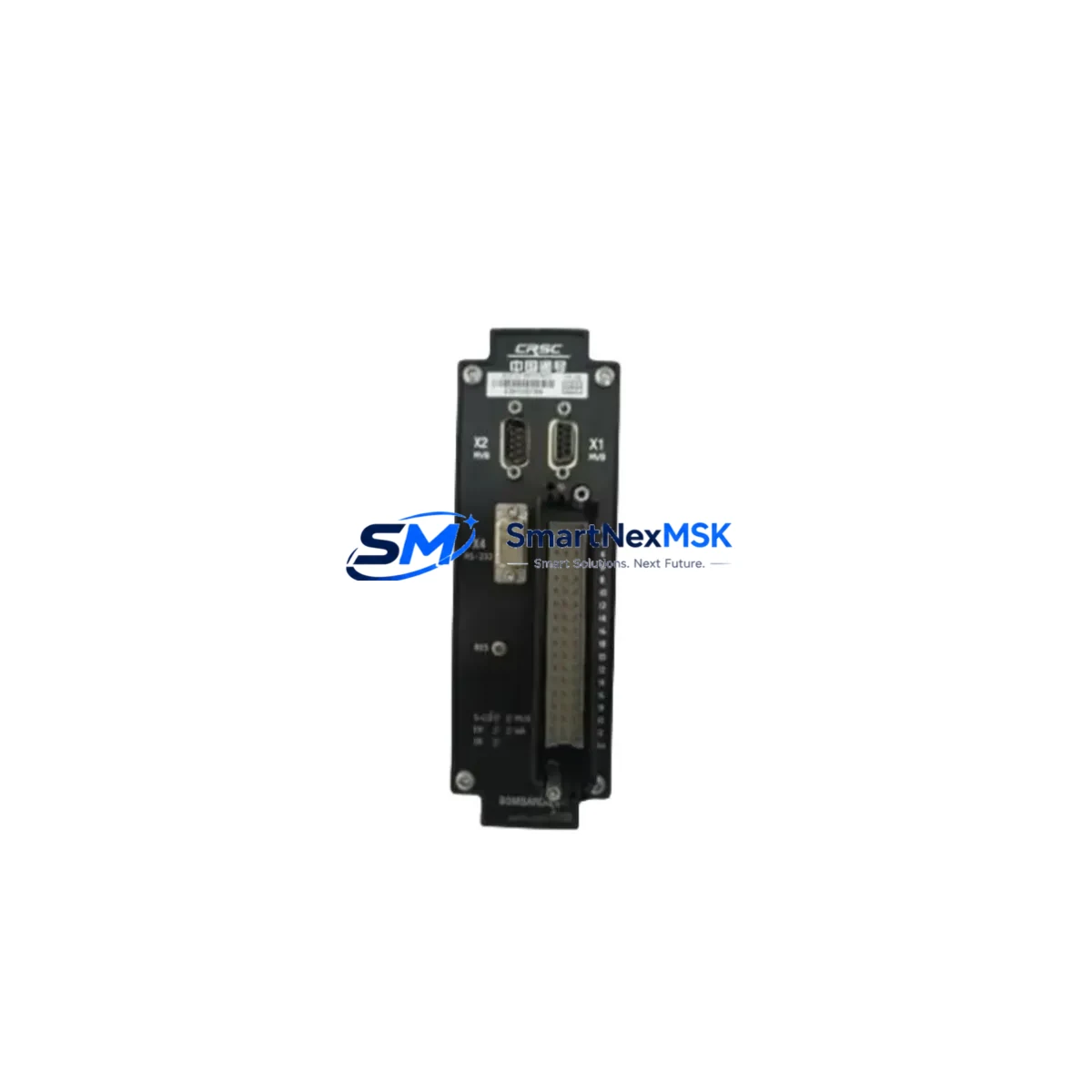
The BOMBARDIER 3EST27-99 is a Transmission Interface Module engineered for the EST Series propulsion and traction control platform. As legacy rail and industrial automation systems approach end-of-life, the 3EST27-99 serves as a verified drop-in retrofit solution for operators managing aging control cabinets, discontinued spare parts, and system modernization programs. Whether you are replacing a failed unit, upgrading a control architecture, or migrating from an obsolete communication protocol, the 3EST27-99 delivers the electrical and functional compatibility required for a smooth, low-risk transition.
Sourced directly from authorized channels and subject to full functional testing prior to shipment, each unit is backed by a 12-month warranty. Our inventory is maintained to support urgent replacement scenarios, minimizing unplanned downtime for critical rail propulsion and industrial drive systems.
Upgrade Compatibility Table
| Parameter | Details |
|---|---|
| SKU / Part Number | 3EST27-99 |
| Brand / Manufacturer | BOMBARDIER |
| Series | EST Series |
| Module Type | Transmission Interface Module |
| Country of Origin | Germany (DE) |
| Backplane / Rack Interface | Compatible with EST Series control rack; verify slot assignment and backplane connector pinout before installation |
| Communication Compatibility | EST Series internal bus; confirm protocol version with existing TCMS or propulsion controller firmware |
| Power Supply Requirement | Verify DC bus voltage and current draw against existing power supply module capacity before hot-swap |
| Terminal Wiring | Match terminal block layout to original wiring diagram; re-use existing cable harness where possible |
| Replacement Recommendation | Direct replacement for failed or end-of-life 3EST27-99 units; confirm firmware revision compatibility |
| Commissioning Focus | Module address configuration, I/O mapping verification, HMI screen parameter update, communication link test |
| Warranty | 12 Months from date of shipment |
| Pre-Shipment Testing | Full functional test performed on every unit |
Retrofit Planning for Existing Automation Systems
Successful integration of the BOMBARDIER 3EST27-99 into an existing EST Series control cabinet requires a structured retrofit plan. Begin by auditing the current control architecture: document the rack configuration, identify the slot position of the outgoing module, and record the existing wiring harness terminations. The EST Series backplane uses a defined slot-addressing scheme, so the replacement module must be assigned the correct logical address to ensure the propulsion controller and TCMS recognize it without requiring a full software re-commission.
Power budget verification is a critical pre-installation step. The EST Series power supply module — typically a dedicated DC/DC converter board within the same control cabinet — must have sufficient headroom to support the 3EST27-99 alongside other active modules such as the I/O expansion boards, digital input modules, and analog output cards already installed in the rack. If the existing power supply is operating near capacity, a parallel power supply module may be required before the retrofit proceeds.
Terminal wiring adaptation is straightforward when the original wiring diagram is available. The 3EST27-99 uses a standard terminal block interface consistent with the EST Series family. Technicians should label all conductors before disconnection, photograph the existing termination layout, and verify continuity after re-termination. Where the original cable harness is in good condition, it can be re-used directly, reducing retrofit labor time significantly.
Communication link integrity must be validated after physical installation. The EST Series internal communication bus connects the transmission interface module to the main propulsion controller, the traction motor drive unit, and — in many configurations — the vehicle HMI panel. After module replacement, the HMI screen parameters related to transmission status, fault codes, and diagnostic readouts should be reviewed and updated to reflect the new module’s firmware revision. In systems where a programming cable (such as a dedicated EST Series diagnostic interface cable) is used for configuration, ensure the cable and associated software version are compatible with the 3EST27-99 firmware.
For systems undergoing broader modernization — for example, migrating from legacy serial communication to a CAN bus or MVB (Multifunction Vehicle Bus) protocol — the 3EST27-99 retrofit may be one step in a larger upgrade path that also involves replacing the main propulsion controller board, updating the TCMS software, and reconfiguring the I/O mapping across all modules in the rack. In these scenarios, the 3EST27-99 should be installed and verified in isolation before the broader protocol migration is executed, ensuring a stable baseline for the subsequent upgrade phases.
Downtime Control During System Migration
Minimizing unplanned downtime is the primary operational concern when replacing a Transmission Interface Module in an active EST Series control system. The recommended approach is to pre-stage the replacement 3EST27-99 unit with the correct module address and configuration parameters before the maintenance window begins. Where the existing system allows, export the current program logic and parameter set from the propulsion controller using the available diagnostic interface, and retain a verified backup before any hardware is disturbed.
During the physical swap, isolate the control cabinet from the main power bus following the applicable lockout/tagout procedure. Remove the failed module, install the 3EST27-99 in the same rack slot, and re-terminate the wiring harness. Power-up sequencing should follow the EST Series commissioning procedure: energize the power supply module first, allow the backplane to initialize, then bring the propulsion controller online. Monitor the HMI panel for fault codes during the first power cycle — any address conflict or communication timeout will be flagged immediately, allowing rapid diagnosis before the system is returned to service.
For critical applications where continuous control is required, a parallel commissioning approach can be used: install and configure the 3EST27-99 in a test rack alongside the live system, validate all I/O signals and communication links in simulation, then execute the final swap during a scheduled maintenance window. This approach protects the original program logic, preserves field control continuity, and reduces the risk of extended downtime caused by unexpected compatibility issues.
Our team provides pre-shipment functional testing and configuration support documentation with every 3EST27-99 unit, ensuring that your maintenance team has the information needed to complete the retrofit efficiently and return the system to full operational status within the planned maintenance window.
Retrofit Support FAQ
Q1: Is the BOMBARDIER 3EST27-99 a direct drop-in replacement for the original EST Series Transmission Interface Module?
A: Yes. The 3EST27-99 is designed as a direct replacement for the original EST Series Transmission Interface Module position. Verify the firmware revision of the replacement unit against the existing propulsion controller software version before installation. In most cases, no program modification is required; however, module address configuration should be confirmed against the original rack layout documentation.
Q2: What wiring and terminal adaptation is required during installation?
A: The 3EST27-99 uses the standard EST Series terminal block interface. The existing cable harness can typically be re-used without modification. Document and photograph all terminations before disconnection, verify conductor labeling, and perform a continuity check after re-termination. No special adapter or wiring harness is required for a like-for-like replacement.
Q3: How is communication link compatibility verified after module replacement?
A: After installation, power up the system in sequence and monitor the HMI panel and propulsion controller diagnostic interface for communication fault codes. Use the EST Series diagnostic cable and associated software to confirm that the 3EST27-99 is recognized on the internal bus, that all I/O channels are mapped correctly, and that transmission status data is being reported accurately to the TCMS. Any address or protocol mismatch will be flagged during the initial power-on self-test.
Q4: What does the 12-month warranty cover, and is pre-shipment testing included?
A: Every BOMBARDIER 3EST27-99 unit supplied by SMARTNEXMSK undergoes full functional testing prior to shipment. The 12-month warranty covers manufacturing defects and functional failures under normal operating conditions from the date of shipment. Units are shipped with test documentation. For warranty claims, contact our technical support team with the unit serial number and a description of the fault condition.
© 2026 SMARTNEXMSK. All rights reserved.
Original Source: https://smartnexmsk.com
Contact: sales@smartnexmsk.com | +86 18259474341