BOSCH 950.000.5 Maintenance-Ready Spare for CNC Automation
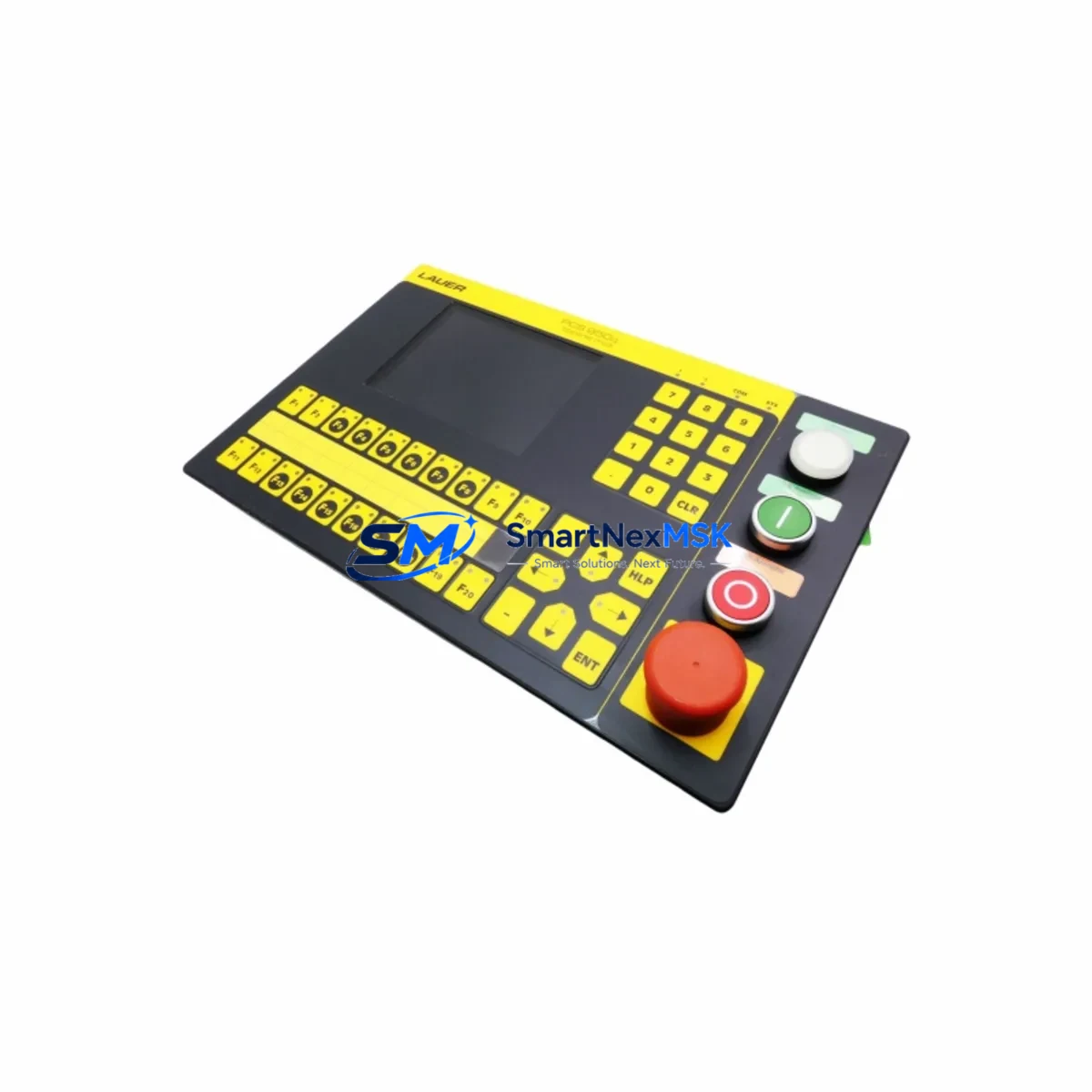
The BOSCH 950.000.5 CNC Operator Panel is a critical human-machine interface component in BOSCH CNC control systems, widely deployed across precision machining centers, turning cells, and multi-axis milling lines. When this panel fails or degrades — whether through display faults, keypad wear, membrane damage, or communication dropout — the entire CNC cell is at risk of unplanned downtime. Sourcing a verified, original-specification replacement is the fastest path to restoring production continuity.
This listing provides a maintenance-ready, original-specification BOSCH 950.000.5 operator panel, fully tested prior to shipment and backed by a 12-month warranty. Whether you are executing a planned overhaul, responding to an emergency fault, or building a strategic spare parts buffer for aging BOSCH CNC equipment, this unit is ready for immediate deployment.
For maintenance engineers and procurement teams managing BOSCH CNC assets, the 950.000.5 is not an isolated component — it sits at the center of a tightly integrated control architecture. A disciplined replacement workflow must account for the full electrical and communication environment surrounding this panel to ensure a clean, stable restart.
Spare Maintenance Table
| Parameter | Specification / Detail |
|---|---|
| Part Number / SKU | 950.000.5 |
| Brand | BOSCH |
| Product Type | CNC Operator Panel |
| Series Compatibility | BOSCH CNC Series (CC, BFW, and compatible legacy platforms) |
| Origin | Germany |
| Interface / Communication | Proprietary BOSCH CNC bus; panel-to-NCU serial link |
| Mounting | Panel-mount, front-of-cabinet installation |
| Operating Voltage | 24 VDC (nominal, supplied via control cabinet backplane or dedicated PSU) |
| Application Environment | Industrial CNC machining centers, turning cells, milling lines |
| Condition | Original specification; tested before shipment |
| Warranty | 12 Months |
| Maintenance Recommendation | Inspect membrane keypad, display backlight, and communication cable on every scheduled PM cycle |
| Replacement Scenario | Display failure, keypad unresponsive, communication dropout, physical damage, planned overhaul |
| Lead Time | In-stock units ship within 1–3 business days; contact for volume orders |
Maintenance Planning for Continuous Operation
A BOSCH 950.000.5 replacement should never be treated as a single-component swap. Experienced maintenance engineers know that operator panel failures are frequently symptomatic of broader issues in the control cabinet. Before returning the CNC cell to production, the following associated components and subsystems should be inspected or proactively replaced as part of the same maintenance window:
24 VDC Power Supply Unit (PSU): The operator panel draws its logic power from the cabinet’s 24 VDC rail. A degraded or undersized PSU — common in aging BOSCH CNC cabinets — can cause intermittent panel resets, display flicker, and communication errors that mimic panel hardware failure. Verify output voltage stability under load before commissioning the replacement 950.000.5.
Panel Communication Cable and Connector: The serial or proprietary bus cable linking the 950.000.5 to the BOSCH NCU (Numerical Control Unit) is a frequent failure point. Inspect for pin corrosion, insulation cracking, and connector seating. A faulty cable will prevent the new panel from initializing correctly and can be misdiagnosed as a panel defect.
BOSCH NCU / CNC Control Unit: If the operator panel failure was preceded by axis alarms, program execution errors, or communication faults, the NCU itself should be evaluated. Replacing the 950.000.5 without addressing an NCU fault will result in repeated panel failures. Keep a spare NCU module in your critical-parts buffer for BOSCH CNC lines with high utilization.
I/O Modules and Terminal Blocks: CNC operator panels interface with machine I/O for cycle start, feed hold, emergency stop, and mode selection. Inspect the associated I/O module inputs and terminal block connections for loose wiring, oxidized contacts, and blown fuses. A single open circuit in the E-stop chain will prevent the machine from entering AUTO mode after panel replacement.
Relay and Contactor Bank: Spindle enable, coolant, and axis brake relays are often located in the same cabinet section as the operator panel wiring. During a panel replacement, inspect relay coil resistance and contact condition. Worn relay contacts cause intermittent faults that are difficult to diagnose after the panel is back online.
Fuse and Circuit Protection: Check all 24 VDC and 110/220 VAC fuses in the control cabinet. A blown fuse on the panel supply circuit is a common root cause of apparent panel failure. Replace any fuses that show signs of heat discoloration or that measure outside rated values.
Membrane Keypad and Overlay: If the 950.000.5 panel uses a membrane keypad overlay, inspect the replacement unit’s keypad for correct tactile response across all keys. Dead zones or sticky keys indicate membrane delamination and should be documented before installation.
Signal Isolation Modules: In environments with high electromagnetic interference — common near large servo drives, spindle inverters, or welding equipment — signal isolators on the panel communication lines protect against noise-induced data corruption. Verify that any installed isolators are functioning and that their input/output signal levels are within specification.
Servo Drive and Axis Amplifier Status: After panel replacement, perform a full axis jog test before running a production program. Latent servo drive faults — such as BOSCH servo amplifier overcurrent or encoder feedback errors — may surface during the first powered cycle and should be resolved before production restart.
Battery-Backed SRAM / Parameter Memory: BOSCH CNC systems store machine parameters, tool offsets, and part programs in battery-backed SRAM. Confirm that the backup battery in the NCU is within its service life and that all parameters are intact after the panel swap. A dead battery can cause parameter loss on the next power cycle, resulting in a machine that requires full recommissioning.
Site Replacement Workflow
Step 1 — Pre-Replacement Documentation: Before powering down, photograph the existing panel wiring, connector positions, and any visible fault codes on the display. Record the current machine parameter backup if the NCU allows a live export. This documentation is essential if parameter recovery is needed after the swap.
Step 2 — Safe Isolation: Follow your site’s lockout/tagout (LOTO) procedure. Isolate the main cabinet power and verify zero-energy state with a calibrated voltage tester. Do not rely on the E-stop alone for panel replacement work.
Step 3 — Panel Removal: Disconnect the communication cable, 24 VDC supply connector, and any auxiliary I/O connectors from the rear of the 950.000.5. Note the cable routing and label each connector if not already marked. Remove the panel mounting hardware and extract the unit from the cabinet door or mounting frame.
Step 4 — Replacement Installation: Mount the new BOSCH 950.000.5 in the same position. Reconnect all cables in the documented order. Verify that the communication cable is fully seated and that the locking mechanism (if present) is engaged. Torque mounting hardware to the manufacturer’s specification.
Step 5 — Power-Up and Verification: Restore cabinet power and observe the panel boot sequence. The display should initialize and present the BOSCH CNC startup screen within the expected time. If the panel displays a communication fault, recheck the NCU cable connection before assuming a panel defect.
Step 6 — Functional Test: Cycle through all operator panel functions: mode selection (JOG, MDI, AUTO), axis jog, spindle override, feed override, and cycle start/stop. Verify that all keys register correctly and that the display updates in real time. Run a dry-cycle (no material) of a representative part program before returning the machine to production.
Step 7 — Documentation and Spare Parts Update: Record the replacement in your maintenance log with the date, technician name, and new unit serial number. Update your spare parts inventory to reflect the consumed unit and initiate a reorder to maintain your buffer stock level.
Spare Parts Support FAQ
Q1: What is the warranty coverage for the BOSCH 950.000.5 supplied by SMARTNEXMSK?
All units are covered by a 12-month warranty from the date of shipment. The warranty covers manufacturing defects and functional failures under normal operating conditions. Each unit is tested before shipment to verify electrical integrity and communication function. If a unit fails within the warranty period, contact our team for a replacement or repair assessment.
Q2: How do I confirm compatibility between the 950.000.5 and my specific BOSCH CNC machine?
Compatibility is confirmed by matching the part number on the existing panel’s nameplate or in the machine’s spare parts manual. If your machine uses a variant or revision of the 950.000.5, provide us with the full nameplate data — including any suffix codes — and our technical team will verify the correct replacement before shipment. Do not install a panel with a different revision code without confirming compatibility with the NCU firmware version.
Q3: What is the recommended spare parts stocking strategy for BOSCH CNC operator panels?
For production lines with two or more BOSCH CNC machines of the same model, we recommend maintaining a minimum of one 950.000.5 panel in on-site buffer stock. For single-machine operations, a consignment or rapid-delivery arrangement with a verified supplier is an acceptable alternative. Operator panels are wear items with a typical service life of 8–15 years depending on operating environment; proactive replacement during scheduled overhauls is more cost-effective than emergency sourcing during unplanned downtime.
Q4: Can the BOSCH 950.000.5 be used to replace older or discontinued BOSCH CNC panel variants?
In many cases, yes — BOSCH maintained a degree of backward compatibility across CNC panel generations, and the 950.000.5 may serve as a direct or near-direct replacement for earlier panel variants used in the same CNC series. However, firmware compatibility between the panel and the NCU must be verified before installation. Our team can advise on cross-reference compatibility based on your machine model and NCU version. Always perform a full functional test after any cross-variant replacement before returning the machine to production.
© 2026 SMARTNEXMSK. All rights reserved.
Original Source: https://smartnexmsk.com
Contact: sales@smartnexmsk.com | +86 18259474341