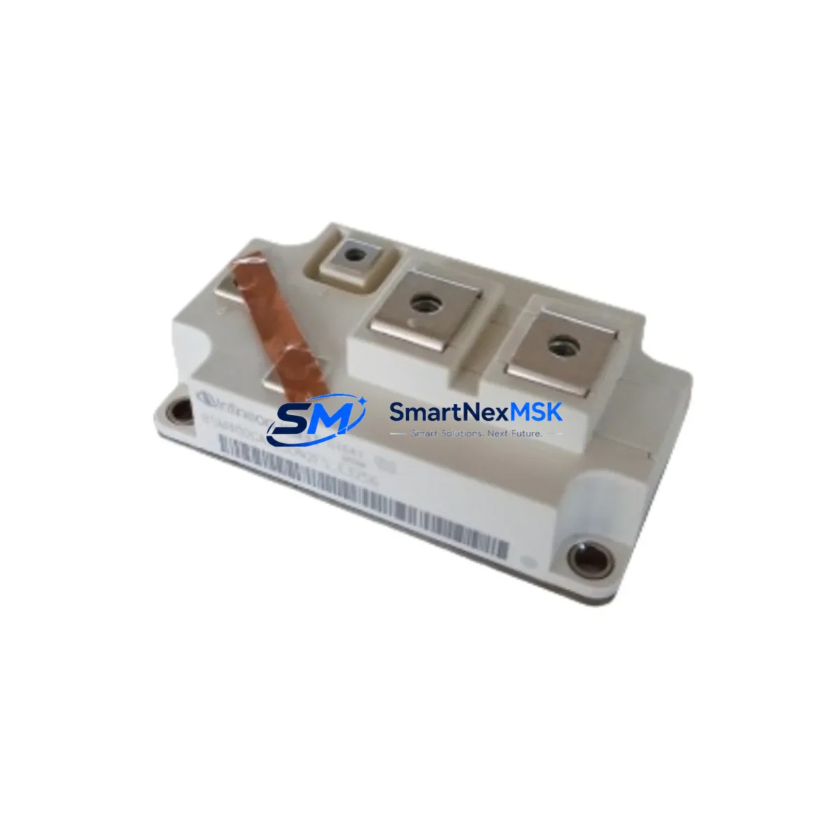
Bosch BSM400GA120DN2FSE3256 Maintenance-Ready Spare for BSM Series Automation
The Bosch BSM400GA120DN2FSE3256 is an original 400A / 1200V half-bridge IGBT power module engineered for high-demand industrial automation environments. As a maintenance-ready spare, it is designed to support rapid field replacement in drive systems, servo amplifiers, and power conversion cabinets where unplanned downtime carries significant operational and financial risk. Sourced directly from verified supply channels, each unit undergoes pre-shipment functional testing and ships with a 12-month warranty, giving maintenance engineers and procurement teams the confidence to stock this module as a critical spare.
In industrial facilities running continuous production lines, motor drive systems, or CNC machining centers, the IGBT power module is one of the highest-stress components in the power stage. Thermal cycling, load transients, and aging gate drivers all contribute to module degradation over time. Proactive spare parts management — including stocking the BSM400GA120DN2FSE3256 — is a proven strategy for reducing mean time to repair (MTTR) and protecting production uptime.
Spare Maintenance Table
| Parameter | Specification |
|---|---|
| Part Number / SKU | BSM400GA120DN2FSE3256 |
| Brand | Bosch / IXYS (BSM Series) |
| Module Type | Half-Bridge IGBT Power Module |
| Collector Current (IC) | 400 A |
| Collector-Emitter Voltage (VCES) | 1200 V |
| Series | BSM (BSM…DN2 / FSE package) |
| Package / Footprint | FSE3256 (compatible with standard BSM half-bridge footprint) |
| Application Environment | Industrial drives, servo amplifiers, UPS, power converters, traction |
| Compatibility | Direct replacement for BSM400GA120DN2 series variants |
| Origin | Germany (DE) |
| Mounting | Baseplate, screw-mount to heatsink |
| Thermal Interface | Requires thermal compound / pad on heatsink contact surface |
| Gate Drive Voltage | +15V / −8V recommended (standard IGBT gate drive) |
| Pre-Shipment Testing | Yes — functional and insulation tested before dispatch |
| Warranty | 12 Months |
| Condition | Original / New |
Maintenance Planning for Continuous Operation
When replacing the BSM400GA120DN2FSE3256 in a drive cabinet or power conversion system, a disciplined maintenance engineer will not stop at the module itself. The surrounding power stage and control circuitry should be inspected simultaneously to prevent repeat failures and ensure the replacement module operates within its rated parameters from day one.
Begin with the DC bus capacitor bank — electrolytic capacitors in the same power stage age in parallel with the IGBT module and may exhibit elevated ESR or reduced capacitance after years of service. Inspect and measure before re-energizing. Next, verify the gate driver board or gate driver IC: a degraded gate driver that delivers insufficient gate voltage or slow switching edges will stress the new module immediately. Check for proper +15V / −8V gate drive levels under load.
The heatsink and thermal management system deserve close attention. Clean the heatsink surface, replace thermal compound, and verify that cooling fans or liquid cooling circuits are functioning correctly — a new IGBT module installed on a fouled heatsink will fail prematurely. If the system uses a Bosch Rexroth IndraDrive or HCS series servo drive, confirm that firmware and current limit parameters are correctly configured for the replacement module’s characteristics.
On the AC input side, inspect line fuses and fast-acting semiconductor fuses (e.g., Bussmann 170M series) and any AC input reactors or EMC line filters for signs of thermal stress or degradation. A blown or weakened fuse that was not replaced after the original module failure is a common cause of repeat damage. Similarly, check current transducers and Hall-effect current sensors used for overcurrent protection — if these have drifted, the protection thresholds may be incorrect.
For systems with a Bosch Rexroth IndraControl or Siemens SIMATIC PLC interface, verify that fault codes have been cleared and that the drive’s self-test routine completes without error before returning the machine to production. If the cabinet includes Phoenix Contact or Weidmüller terminal blocks, shielded signal cables, or fiber-optic gate drive links (e.g., HFBR-series transceivers), inspect for loose connections or damaged insulation that could introduce noise into the gate drive circuit. Finally, review the snubber circuit or clamp diode across the DC bus — these components absorb switching transients and may have been stressed during the original failure event.
Stocking the BSM400GA120DN2FSE3256 alongside complementary spares — such as a spare gate driver board, a set of DC bus film capacitors, a replacement fast-acting semiconductor fuse, and a spare Bosch Rexroth power supply module (HNS or HMV series) — transforms a potential multi-day outage into a same-shift recovery.
Site Replacement Workflow
1. Isolate and de-energize: Follow LOTO procedures. Discharge the DC bus fully (verify with a calibrated meter — bus capacitors can hold lethal charge for several minutes after power-off).
2. Document the existing configuration: Photograph wiring, note gate drive connector orientation, and record any parameter settings from the drive controller before disassembly.
3. Remove the failed module: Unscrew the baseplate mounting bolts, disconnect gate and auxiliary emitter connections, and carefully lift the module from the heatsink. Inspect the heatsink surface for burn marks or contamination.
4. Prepare the heatsink: Clean the contact surface with isopropyl alcohol, apply a thin, even layer of thermal compound, and verify the mounting surface is flat and free of debris.
5. Install BSM400GA120DN2FSE3256: Position the module, torque mounting screws to the manufacturer’s specification (typically 3–5 Nm for this package size), and reconnect gate and auxiliary emitter leads in the correct polarity.
6. Verify gate drive and protection settings: Before energizing, confirm gate drive voltage levels, overcurrent trip thresholds, and desaturation protection are correctly set for the replacement module.
7. Controlled power-up and test: Energize at reduced load, monitor for fault codes, verify output waveforms, and confirm thermal performance before returning to full production load.
This workflow minimizes re-failure risk and ensures the replacement BSM400GA120DN2FSE3256 delivers its full rated service life in your application.
Spare Parts Support FAQ
Q1: Is the BSM400GA120DN2FSE3256 a direct drop-in replacement for older BSM400GA120DN2 variants?
A: Yes. The FSE3256 suffix denotes the package and internal construction variant, but the electrical ratings (400A / 1200V, half-bridge topology) and mounting footprint are compatible with standard BSM400GA120DN2 series applications. Always verify gate drive requirements and thermal interface specifications against your specific drive design before installation.
Q2: What pre-shipment testing is performed on each unit?
A: Every BSM400GA120DN2FSE3256 unit is functionally tested for gate-emitter integrity, collector-emitter blocking voltage, and forward voltage drop before dispatch. An insulation resistance check is also performed. Test records are available upon request for quality-critical applications.
Q3: How should this module be stored as a long-term spare?
A: Store in the original anti-static packaging in a dry environment (relative humidity <75%, non-condensing) at temperatures between −25°C and +70°C. Avoid mechanical shock. Inspect the module visually and perform a basic gate-emitter resistance check annually if stored for more than 12 months.
Q4: What is covered under the 12-month warranty?
A: The 12-month warranty covers manufacturing defects and premature failure under normal operating conditions within the module’s rated parameters. It does not cover damage resulting from incorrect installation, overvoltage events, inadequate thermal management, or operation outside rated specifications. Contact our technical team for warranty claims and RMA support.
© 2026 SMARTNEXMSK. All rights reserved.
Original Source: https://smartnexmsk.com
Contact: sales@smartnexmsk.com | +86 18259474341