Bosch Rexroth MV-VPB40*3-PB002 Maintenance-Ready Spare VPB Series: Spare Replacement & Industrial Downtime Risk Control
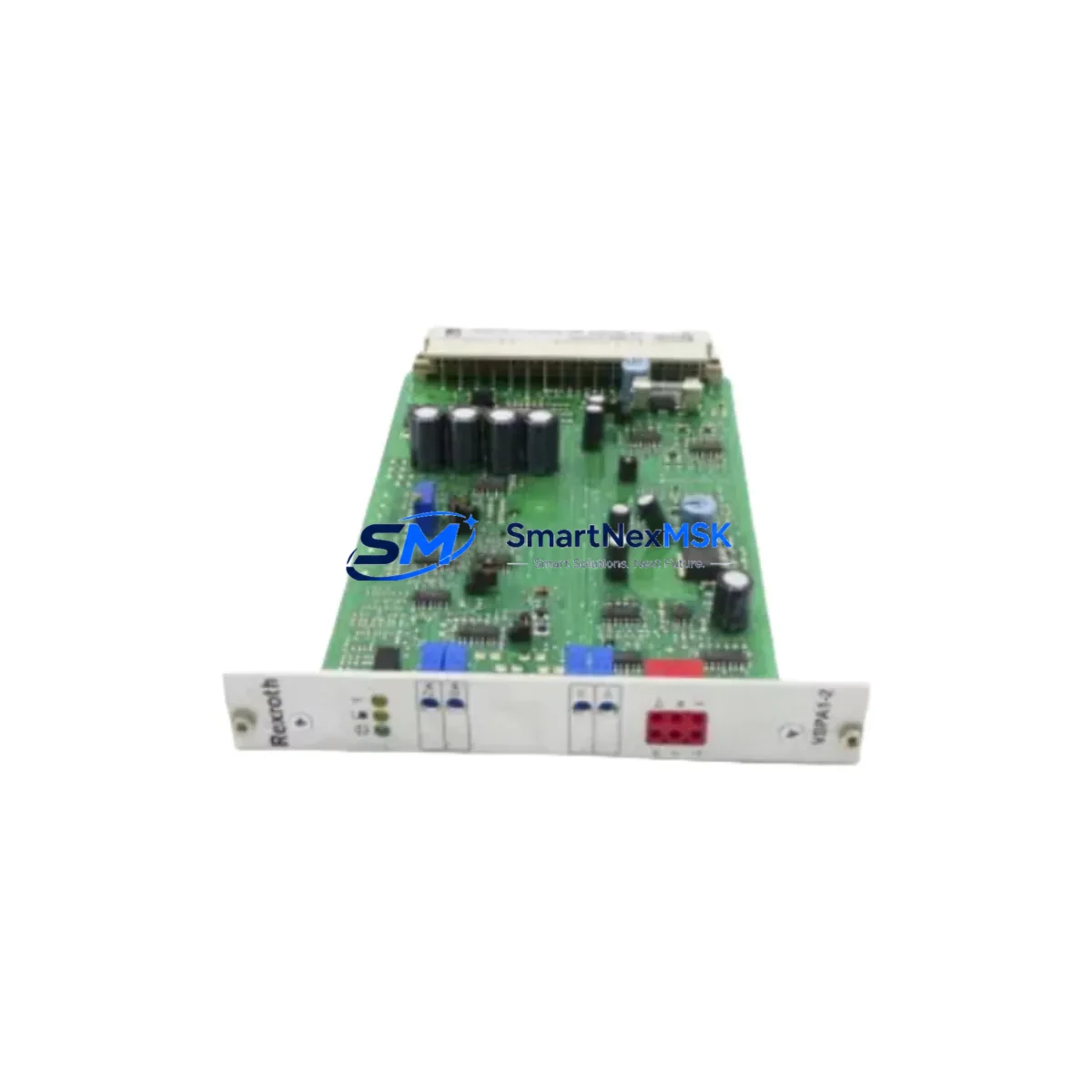
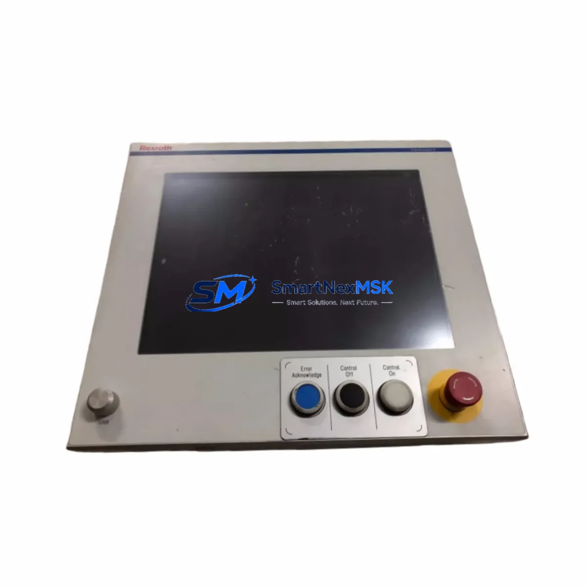
The Bosch Rexroth MV-VPB40*3-PB002 (also referenced as VPB-38/43-AC2-715, R91133860) is an original HMI operator panel designed for integration within Rexroth VPB Series control architectures. In industrial environments where continuous machine availability is non-negotiable, maintaining a verified spare of this panel in your parts inventory is a fundamental risk-mitigation strategy. Whether you are managing a CNC machining center, a hydraulic press line, or a multi-axis motion control system, the VPB Series HMI is the primary human-machine interface through which operators monitor process parameters, acknowledge alarms, and initiate controlled shutdowns. A failed or degraded panel can halt production entirely — making rapid, like-for-like replacement critical to minimizing mean time to repair (MTTR).
This unit ships as an original Bosch Rexroth component, fully tested prior to dispatch, and is backed by a 12-month warranty covering manufacturing defects and functional integrity. Each unit undergoes pre-shipment functional verification to confirm display output, keypad response, communication interface continuity, and power-on self-test (POST) completion before leaving our facility.
Spare Maintenance Table
| Parameter | Specification / Detail |
|---|---|
| Part Number | MV-VPB40*3-PB002 |
| Cross Reference | VPB-38/43-AC2-715 | R91133860 |
| Brand | Bosch Rexroth |
| Series | VPB Series (Visual Panel Box) |
| Product Type | Industrial HMI Operator Panel |
| Display Size | ~10.4″ (VPB40 class, application-dependent) |
| Communication Interface | PROFIBUS-DP (PB002 suffix), RS-232/RS-485 auxiliary |
| Supply Voltage | 24 VDC nominal (AC2 variant: AC input supported) |
| Operating Temperature | 0°C to +55°C (panel-mount, forced-air recommended above 45°C) |
| Protection Rating | IP65 front panel (NEMA 4 equivalent) |
| Country of Origin | Germany |
| Compatibility | Rexroth VPB Series control cabinets; Rexroth IndraControl, IndraMotion, and legacy CNC platforms |
| Installation | Panel cutout mount; DIN rail adapter available for retrofit |
| Warranty | 12 Months — covers manufacturing defects and functional failure |
| Pre-Shipment Test | Power-on, display, keypad, and communication interface verified |
| Lead Time | In-stock units ship within 1–3 business days |
Maintenance Planning for Continuous Operation
When a maintenance or procurement engineer schedules replacement of the MV-VPB40*3-PB002, the replacement event should be treated as a broader control cabinet inspection opportunity. The VPB Series HMI does not operate in isolation — it is electrically and communicatively integrated with a network of components whose condition directly affects panel reliability and post-replacement stability.
Begin with the 24 VDC panel power supply: verify output voltage under load, check for ripple exceeding 200 mV, and inspect terminal connections for oxidation or thermal discoloration. A degraded power supply is a common root cause of intermittent HMI resets and display corruption that is frequently misdiagnosed as a panel fault. If the cabinet uses a Rexroth or third-party switched-mode power supply (SMPS) in the 10A–20A class, replace it concurrently if it has exceeded five years of service.
Next, inspect the PROFIBUS-DP communication cable and connectors running from the HMI to the PLC or motion controller. The PB002 suffix on this panel designates PROFIBUS as the primary fieldbus. Damaged bus terminators, incorrect bus termination at segment ends, or corroded 9-pin Sub-D connectors are frequent causes of communication faults that appear as HMI freezes or loss of process data. Replace bus connectors and verify termination resistor status at both ends of the segment.
Inspect the Rexroth IndraControl or IndraMotion controller that the HMI communicates with. Check the controller’s CPU module status LEDs, battery backup condition (for SRAM retention), and firmware version compatibility with the replacement panel. If the system uses a Rexroth CLC or CSB servo drive module, verify that drive parameter sets are backed up before panel replacement, as some configurations store operator-adjusted parameters locally on the HMI.
Review the I/O expansion modules connected to the same PROFIBUS segment. Rexroth Inline or third-party distributed I/O nodes should be checked for diagnostic LEDs indicating bus errors, which may have been masked by the failed HMI. Inspect signal isolators on analog input channels — particularly 4–20 mA loops feeding process variables displayed on the HMI — for drift or ground loop issues that could cause erroneous readings post-replacement.
Check the cabinet terminal blocks and wiring harness connecting the HMI to the operator station. Inspect for loose ferrules, insulation cracking on flexible cables, and correct labeling. If the installation uses a membrane keypad extension or remote operator station connected via ribbon cable, inspect the connector seating and cable routing for pinch points.
For sites running legacy Rexroth systems, also verify the condition of the PROFIBUS repeater or optical link module if the HMI is located more than 50 meters from the controller or on a separate cable segment. Repeater degradation is a silent failure mode that causes intermittent communication loss only under high bus load conditions.
Finally, confirm that the UPS or battery backup module supplying the control cabinet is functional and that its battery capacity has been tested within the last 12 months. An unprotected HMI replacement performed during a live production shift without UPS coverage risks data loss and parameter corruption if a power transient occurs during commissioning.
Site Replacement Workflow
Step 1 — Pre-replacement documentation: Before removing the existing MV-VPB40*3-PB002, photograph the current screen configuration, record all operator-set parameters, and export any project files stored on the panel if the firmware supports it. Confirm the replacement unit’s firmware version matches or is compatible with the installed controller firmware.
Step 2 — Isolation and de-energization: Isolate the HMI power supply at the cabinet disconnect. Verify zero voltage at the panel power terminals using a calibrated multimeter. Disconnect the PROFIBUS connector and any auxiliary serial or USB cables before removing the panel from the cutout.
Step 3 — Physical installation: Install the MV-VPB40*3-PB002 replacement into the existing panel cutout. Verify gasket seating for IP65 integrity. Reconnect all cables in reverse order of removal. Torque terminal screws to the manufacturer’s specification to prevent contact resistance issues.
Step 4 — Communication commissioning: Power on the cabinet and verify PROFIBUS bus status. Confirm the replacement panel is recognized at the correct node address. Restore operator parameters and verify all process variable displays against known-good reference values from the controller.
Step 5 — Functional verification: Cycle through all HMI screens, test alarm acknowledgment, verify trend displays, and confirm remote I/O status pages reflect live field conditions. Document the replacement in the site maintenance log with the new unit’s serial number and installation date.
This workflow is applicable whether replacing a failed unit on an emergency basis or executing a planned preventive replacement as part of a scheduled shutdown. Maintaining one spare MV-VPB40*3-PB002 in your site parts store eliminates the lead-time risk associated with sourcing obsolete or long-delivery HMI panels during an unplanned outage.
Spare Parts Support FAQ
Q1: What is the expected service life of the MV-VPB40*3-PB002, and when should I plan a preventive replacement?
Bosch Rexroth VPB Series HMI panels are designed for a nominal service life of 10–15 years under standard industrial operating conditions. In practice, backlight degradation (visible as reduced display brightness) typically begins after 50,000–70,000 hours of operation. Preventive replacement is recommended when display luminance drops below 50% of original specification, when touchscreen or keypad response becomes inconsistent, or when the panel has exceeded 10 years of continuous service in a high-vibration or high-temperature environment. Stocking one spare unit per production line eliminates emergency sourcing delays.
Q2: How do I verify compatibility between the replacement MV-VPB40*3-PB002 and my existing Rexroth controller?
Compatibility is confirmed by matching three parameters: (1) the PROFIBUS-DP protocol version supported by your controller (DP-V0 or DP-V1), (2) the HMI project software version used to create the panel application, and (3) the physical connector and cable pinout at the panel interface. The R91133860 material number is the Rexroth internal reference for this configuration — use it when cross-referencing against your controller’s approved HMI list or contacting Rexroth technical support for compatibility confirmation.
Q3: What pre-shipment testing is performed on each unit, and what does the 12-month warranty cover?
Every MV-VPB40*3-PB002 unit undergoes a full power-on self-test, display pixel verification, keypad or touchscreen functional check, and PROFIBUS communication interface continuity test before shipment. The 12-month warranty covers manufacturing defects, component failure under normal operating conditions, and functional non-conformance to the original Bosch Rexroth specification. It does not cover damage resulting from incorrect installation voltage, physical impact, or operation outside the rated environmental envelope.
Q4: Can this panel replace older VPB Series variants, and are there any configuration changes required?
The MV-VPB40*3-PB002 is designed as a direct form-fit-function replacement within the VPB-38/43 mechanical envelope. Sites upgrading from earlier VPB40 variants without the PB002 communication suffix should verify that the PROFIBUS interface is enabled in the controller’s I/O configuration and that the GSD file for the replacement panel is loaded into the PROFIBUS master. In most cases, the existing HMI project can be reloaded without modification; however, firmware version alignment between the panel and the project development tool should be confirmed before go-live.
© 2026 SMARTNEXMSK. All rights reserved.
Original Source: https://smartnexmsk.com
Contact: sales@smartnexmsk.com | +86 18259474341