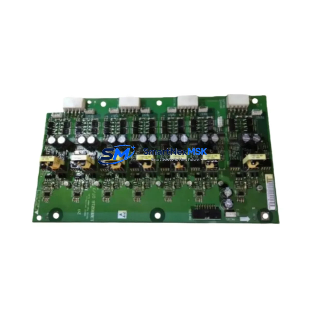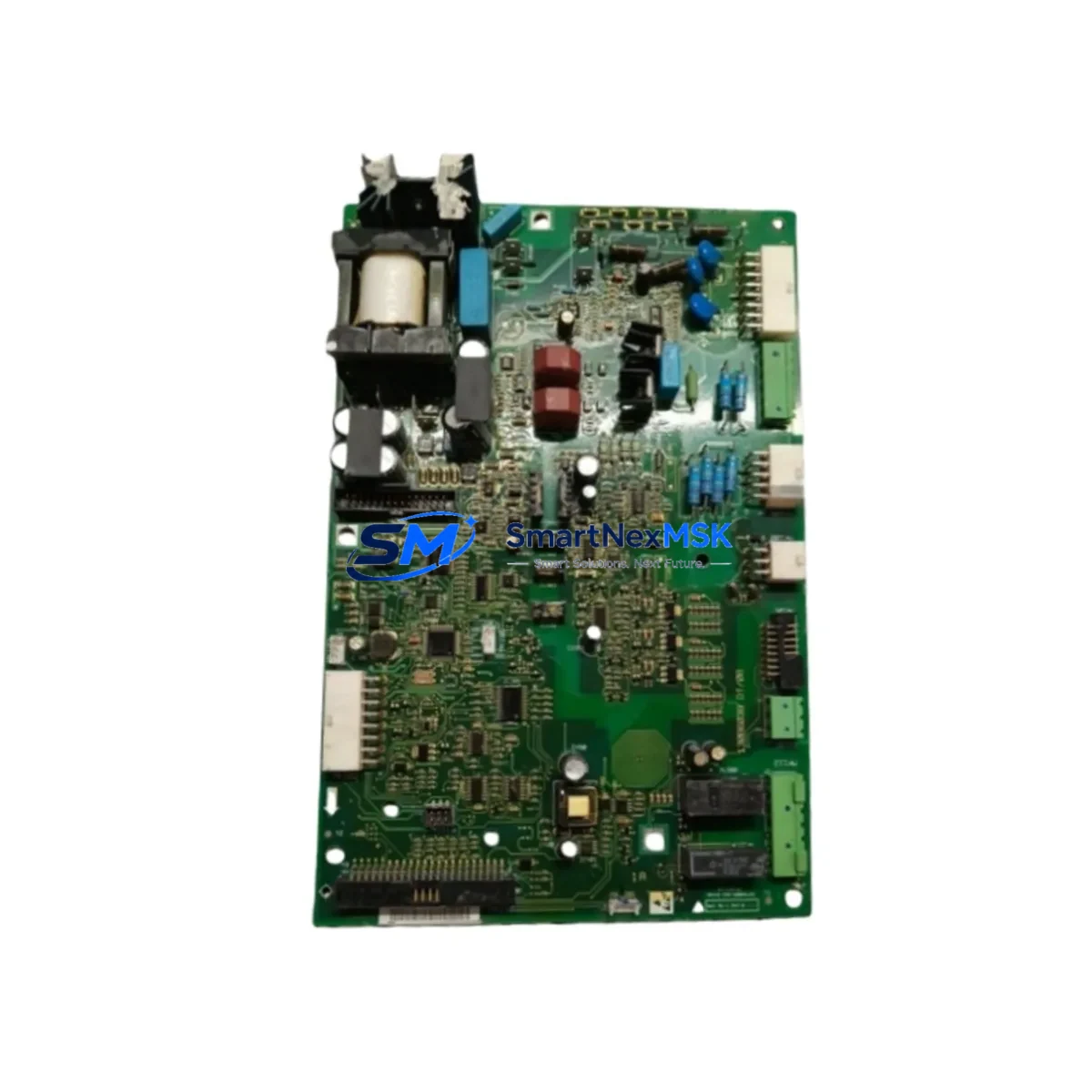
Danfoss 175Z2330 DT1 Retrofit Relay Output for FC Control Systems
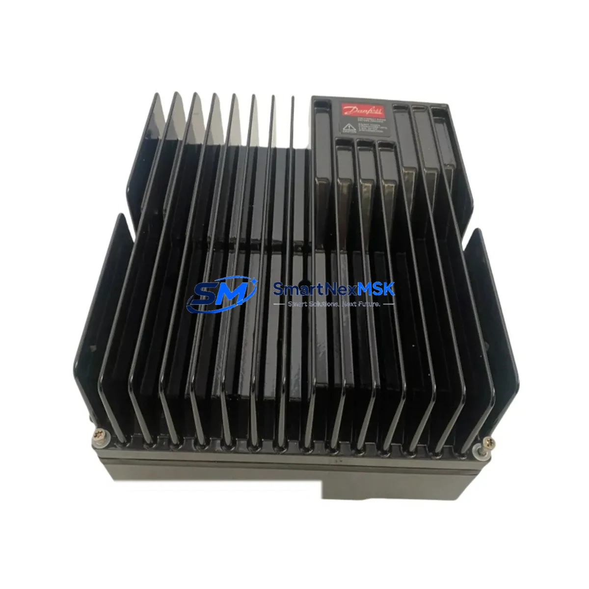
When a Danfoss FC-Series variable frequency drive begins exhibiting relay output faults, intermittent control signal loss, or fails to respond to external interlock commands, the root cause is frequently a degraded or failed relay output board. The Danfoss 175Z2330 DT1 relay output module is the factory-specified replacement board for FC 301, FC 302, and FC 300 series drives — one of the most widely deployed VFD platforms in pump stations, HVAC systems, compressor lines, and conveyor control cabinets across global industrial facilities. Sourced from verified supply channels, tested prior to shipment, and backed by a 12-month warranty, this module is engineered to restore full relay output functionality with minimal downtime and zero programming changes.
Upgrade Compatibility Table
| Parameter | Details |
|---|---|
| SKU / Part Number | 175Z2330 DT1 |
| Brand | Danfoss |
| Compatible Series | FC 301, FC 302, FC 300 |
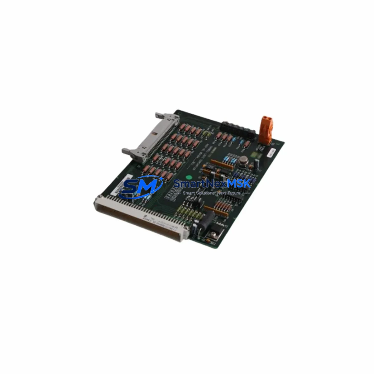
| Module Type | Relay Output Board (Option Card) |
| Relay Output Channels | 3 × SPDT relay outputs (Form C) |
| Contact Rating | 240 VAC / 2 A, 24 VDC / 2 A |
| Installation Interface | Option slot B (drive-specific slot assignment) |
| Communication Compatibility | Integrates with FC drive control logic; no external fieldbus required |
| Retrofit Recommendation | Direct drop-in replacement for failed or degraded DT1 boards |
| Commissioning Notes | Verify parameter group 5-4x relay assignments post-installation |
| Origin | Denmark |
| Warranty | 12-Month Warranty — Covered from date of shipment |
Retrofit Planning for Existing Automation Systems
Replacing the 175Z2330 DT1 in an existing FC-Series drive installation requires a structured approach to ensure the retrofit does not disrupt adjacent control logic or connected field devices. Before removing the old board, engineers should document the current relay output assignments in parameter group 5-4x using the Danfoss LCP (Local Control Panel) — typically an LCP 101 or LCP 102 — or via the MCT 10 Set-up Software connected through the drive’s RS-485 port or USB interface.
In multi-drive panels, the FC 301 and FC 302 drives are often networked via Profibus DP, PROFINET, or Modbus RTU using option cards such as the Danfoss MCA 101 Profibus or MCA 120 PROFINET modules. These communication option cards occupy a separate slot from the relay output board, so the 175Z2330 DT1 replacement can proceed without disturbing the fieldbus configuration. However, the site engineer should confirm that the drive’s option slot B is free and that no conflicting option card — such as an MCB 101 general purpose I/O module or MCB 102 PTC thermistor card — is currently installed in that position.
Power supply integrity is a critical pre-check. The FC-Series drives draw 24 VDC control power from an internal SMPS, but in retrofit scenarios where the drive is integrated with a Danfoss AK-PS 075 power supply or a third-party 24 VDC rail supply, the engineer must verify that the supply can sustain the additional relay coil load introduced by the new board. Relay coil energization draws are typically low, but in dense control cabinets with multiple relay output cards, cumulative load can approach supply limits.
Terminal wiring for the relay outputs — typically wired to motor contactors, safety relays, or PLC digital input modules — should be photographed and labeled before disconnection. The 175Z2330 DT1 uses the same terminal block layout as its predecessor, so rewiring is straightforward. After reinstallation, the engineer should verify continuity on each relay output channel before re-energizing the drive. If the drive is connected to a Siemens S7-300 PLC or Allen-Bradley CompactLogix via hardwired digital I/O, the relay output states should be confirmed in the PLC’s I/O diagnostic screen before resuming automatic control.
For sites running Danfoss FC 302 drives in closed-loop PID control — common in water treatment and HVAC applications — the relay output board is often assigned to signal pump fault, run confirmation, or high-temperature alarm states. These assignments must be re-verified in parameters 5-40 through 5-43 after the board swap. If the site uses a SCADA system or DCS monitoring relay states via Modbus, the engineer should confirm that the relay output register map remains unchanged after the retrofit.
Downtime Control During System Migration
Minimizing production interruption during a relay output board replacement on an FC-Series drive requires advance preparation and a clear sequence of steps. The recommended approach is to schedule the swap during a planned maintenance window, pre-stage the 175Z2330 DT1 replacement board alongside the LCP and a laptop loaded with MCT 10, and prepare a parameter backup file from the drive before any hardware is touched.
The drive’s parameter set — including all relay output assignments, PID setpoints, ramp times, and motor data — should be uploaded to MCT 10 or saved to the LCP’s internal memory using the LCP copy function. This ensures that if the drive requires a factory reset during the board swap, all control logic can be restored within minutes rather than hours. In facilities where the FC drive controls a critical pump or compressor, a bypass contactor or manual override should be engaged to maintain process flow during the swap window.
Once the 175Z2330 DT1 is installed and the drive is powered up, the engineer should perform a relay output function test by manually triggering each relay via the drive’s built-in output test function (accessible through the LCP menu). Confirm that connected field devices — motor starters, alarm panels, or PLC inputs — respond correctly before releasing the drive to automatic control. Total swap time for a prepared technician is typically under 30 minutes, making this one of the lowest-risk retrofit operations in an FC-Series drive cabinet.
All units supplied by SMARTNEXMSK are pre-tested against Danfoss factory specifications, shipped with protective packaging, and covered by a 12-month warranty from the date of shipment. Stock is maintained for fast dispatch to minimize the gap between fault identification and system restoration.
Retrofit Support FAQ
Q1: Is the 175Z2330 DT1 a direct drop-in replacement for the original Danfoss relay output board?
Yes. The 175Z2330 DT1 is the factory-specified relay output option card for FC 301, FC 302, and FC 300 series drives. It installs into option slot B without mechanical modification and uses the same terminal block layout as the original board. No parameter changes are required beyond re-verifying relay output assignments in parameter group 5-4x.
Q2: What pre-shipment testing is performed on this module?
Each 175Z2330 DT1 unit is functionally tested prior to shipment. Testing includes relay coil energization verification, contact continuity checks on all three output channels, and visual inspection for component integrity. A test report is available upon request.
Q3: Can this board be used in FC 302 drives running Profibus or PROFINET communication?
Yes. The relay output board occupies a dedicated option slot and does not interfere with communication option cards such as the MCA 101 Profibus or MCA 120 PROFINET modules installed in other slots. Both cards can operate simultaneously within the same drive.
Q4: What does the 12-month warranty cover?
The warranty covers manufacturing defects, relay contact failure, and board-level component faults under normal operating conditions. It does not cover damage caused by incorrect installation, overvoltage events, or operation outside the specified contact rating. Warranty claims are processed directly through SMARTNEXMSK with replacement or refund options.
© 2026 SMARTNEXMSK. All rights reserved.
Original Source: https://smartnexmsk.com
Contact: sales@smartnexmsk.com | +86 18259474341