Danfoss FCD322PT4P66STR1D0F00T52C0 Spare FC 302 Drive: Spare Replacement & Industrial Downtime Risk Control
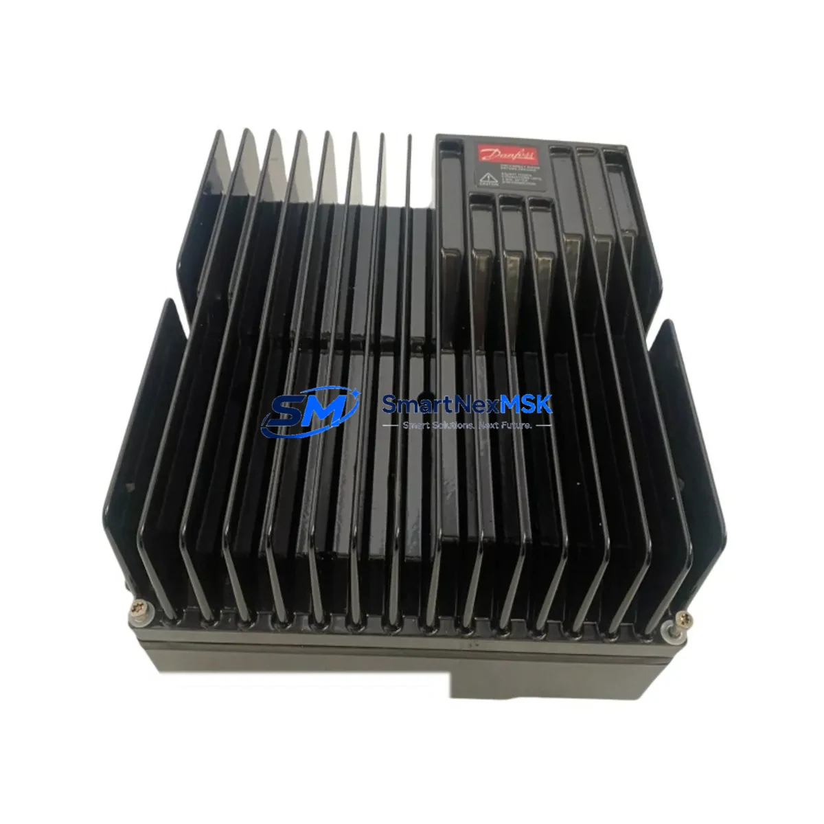
The Danfoss FCD322PT4P66STR1D0F00T52C0 is a 22kW three-phase variable frequency drive from the FC 302 series, rated IP66 for harsh industrial environments. Designed for demanding process automation applications, this unit delivers precise motor speed control, energy efficiency, and robust protection in environments exposed to dust, moisture, and vibration. As a maintenance-ready original spare, it is stocked and tested to support rapid field replacement, minimizing unplanned downtime in continuous production lines, pump stations, HVAC systems, and conveyor automation.
For maintenance engineers managing aging FC 302 installations, having a verified spare on the shelf is the single most effective strategy for downtime risk control. The FCD322PT4P66STR1D0F00T52C0 is a direct replacement for failed or degraded units in the same power class, with full parameter compatibility when using the FC 302 LCP (Local Control Panel) or Danfoss MCT 10 software for parameter transfer. Each unit is pre-tested before dispatch and ships with a 12-month warranty covering manufacturing defects and functional failure.
Spare Maintenance Table
| Parameter | Specification |
|---|---|
| SKU / Part Number | FCD322PT4P66STR1D0F00T52C0 |
| Brand | Danfoss |
| Series | FC 302 (VLT® AutomationDrive) |
| Power Rating | 22kW (30HP) |
| Input Voltage | 3-phase, 380–480V AC |
| Output Frequency | 0–590 Hz |
| Enclosure Rating | IP66 (NEMA 4X equivalent) |
| Control Mode | VVC+, Open Loop, Closed Loop |
| Communication | RS-485 (FC protocol / Modbus RTU) |
| Fieldbus Options | PROFIBUS, DeviceNet, EtherNet/IP (option cards) |
| Braking | Dynamic braking ready (external resistor) |
| Cooling | Forced air cooling |
| Operating Temperature | -10°C to +50°C (derating above 45°C) |
| Origin | Denmark |
| Compatibility | FC 302 series; replaces same-frame 22kW IP66 variants |
| Installation | DIN rail / panel mount; standard FC 302 wiring footprint |
| Warranty | 12 months from date of shipment |
| Pre-shipment Test | Power-on functional test performed before dispatch |
Maintenance Planning for Continuous Operation
When replacing the FCD322PT4P66STR1D0F00T52C0 in the field, a thorough inspection of the surrounding electrical circuit is essential to prevent repeat failures and ensure system stability. Maintenance engineers should treat a VFD replacement as a full drive-circuit audit, not just a unit swap.
Power supply integrity is the first checkpoint. Verify that the upstream Danfoss MCD 500 soft starter or main circuit breaker feeding the drive is within rated capacity and shows no signs of contact wear or thermal damage. Loose or corroded input terminals are a leading cause of premature VFD failure and must be re-torqued to specification during every planned maintenance interval.
Motor cable and output wiring should be inspected for insulation degradation, especially in IP66 installations where cable glands are exposed to washdown cycles. Shielded motor cables with proper grounding at both ends are mandatory for FC 302 drives to suppress EMC interference. If the existing cable run exceeds 50 meters, confirm that output dU/dt filters or sine-wave filters are in place to protect motor winding insulation.
I/O and control wiring deserves careful attention. The FC 302 supports a rich set of analog and digital I/O terminals. During replacement, verify that all 24V DC control signals, analog speed references (0–10V or 4–20mA), and digital run/stop commands are correctly mapped to the new unit’s parameter set. If the site uses a Danfoss FC 302 option card such as the MCO 305 (positioning) or a PROFIBUS DP module, confirm the option card is transferred and re-seated correctly.
Communication and fieldbus continuity must be validated after replacement. For RS-485 Modbus RTU networks, confirm the drive address, baud rate, and parity settings match the SCADA or PLC configuration. Sites running Siemens S7-300/S7-400 PLCs or Allen-Bradley ControlLogix systems via PROFIBUS should perform a full communication test before returning the drive to automatic mode.
Relay outputs and safety circuits are frequently overlooked during VFD replacement. The FC 302 includes programmable relay outputs used for fault signaling, run confirmation, and motor thermistor protection. Verify that the thermistor relay wiring and any external safety relay modules (such as Pilz PNOZ or Sick safety relays) are correctly reconnected and tested. Failure to restore safety relay continuity can result in undetected motor overtemperature conditions.
HMI and parameter backup should be completed before decommissioning the old unit. Use the Danfoss LCP 102 panel or MCT 10 software to export the parameter set from the failed drive if it is still partially functional. This eliminates manual re-entry errors and ensures the replacement unit mirrors the original configuration exactly, including ramp times, current limits, and PID setpoints.
For sites with aging FC 302 installations, consider stocking complementary spares alongside the FCD322PT4P66STR1D0F00T52C0: Danfoss FC 302 LCP display panels, brake resistors for dynamic braking circuits, EMC input filters, and 24V DC power supply modules for the control circuit. A well-structured spare parts kit reduces mean time to repair (MTTR) from hours to minutes.
Site Replacement Workflow
Step 1 — Isolation and lockout: Isolate the drive from the main supply and apply LOTO (Lockout/Tagout) procedure. Wait a minimum of 4 minutes after power-off before opening the enclosure to allow DC bus capacitors to discharge safely. Verify DC bus voltage with a calibrated multimeter before touching internal components.
Step 2 — Parameter backup: If the existing drive is still responsive, connect the LCP or MCT 10 software and perform a full parameter export. Save the file with the asset tag and date for traceability.
Step 3 — Mechanical removal: Disconnect all power cables (L1/L2/L3 input, U/V/W motor output, PE ground), control wiring, and communication cables. Label each terminal group before removal. Remove the drive from the panel using the standard FC 302 mounting hardware.
Step 4 — Replacement unit installation: Mount the FCD322PT4P66STR1D0F00T52C0 in the same panel position. Reconnect all cables in reverse order: PE ground first, then power cables, then control wiring, then communication. Torque all terminals to the values specified in the FC 302 operating guide.
Step 5 — Parameter restore and commissioning: Power up the drive and restore the saved parameter set via LCP or MCT 10. Perform a no-load motor test (motor decoupled if possible) to verify direction of rotation, speed reference response, and fault-free operation. Confirm communication with the PLC or SCADA system before returning to automatic mode.
Step 6 — Documentation: Record the replacement in the site maintenance log, including the old unit’s serial number, failure mode, replacement date, and the new unit’s serial number. Update the spare parts inventory to trigger reorder of a replacement spare.
Spare Parts Support FAQ
Q1: Is the FCD322PT4P66STR1D0F00T52C0 a direct drop-in replacement for other FC 302 22kW IP66 variants?
Yes, within the same power class and enclosure rating, the FCD322PT4P66STR1D0F00T52C0 shares the same mechanical footprint and wiring terminals as other FC 302 22kW IP66 units. Parameter compatibility is maintained across the FC 302 series. Minor differences in option card slots or software version may require a firmware check — contact our technical team for confirmation before installation if your site has specific fieldbus or safety requirements.
Q2: What pre-shipment testing is performed on this spare?
Every unit undergoes a power-on functional test prior to dispatch. This includes DC bus charge verification, output phase balance check, and basic control I/O response test. Units that do not pass are quarantined and not shipped. A test report is available upon request for quality-critical procurement processes.
Q3: What does the 12-month warranty cover?
The 12-month warranty covers manufacturing defects and functional failure under normal operating conditions from the date of shipment. It does not cover damage caused by incorrect installation, overvoltage events, water ingress due to improper cable gland sealing, or unauthorized modification. Warranty claims are processed with photographic evidence and a fault description — our team targets a response within 2 business days.
Q4: How should this spare be stored if not immediately installed?
Store the unit in its original packaging in a dry, temperature-controlled environment (0°C to +55°C, relative humidity below 95% non-condensing). Avoid storage near strong magnetic fields or corrosive atmospheres. For long-term storage exceeding 12 months, it is recommended to power up the drive for 30 minutes annually to re-form the DC bus electrolytic capacitors and prevent capacitance degradation.
© 2026 SMARTNEXMSK. All rights reserved.
Original Source: https://smartnexmsk.com
Contact: sales@smartnexmsk.com | +86 18259474341