Danfoss M8777/153-09-B615A2E1 Maintenance-Ready Spare for VLT Automation
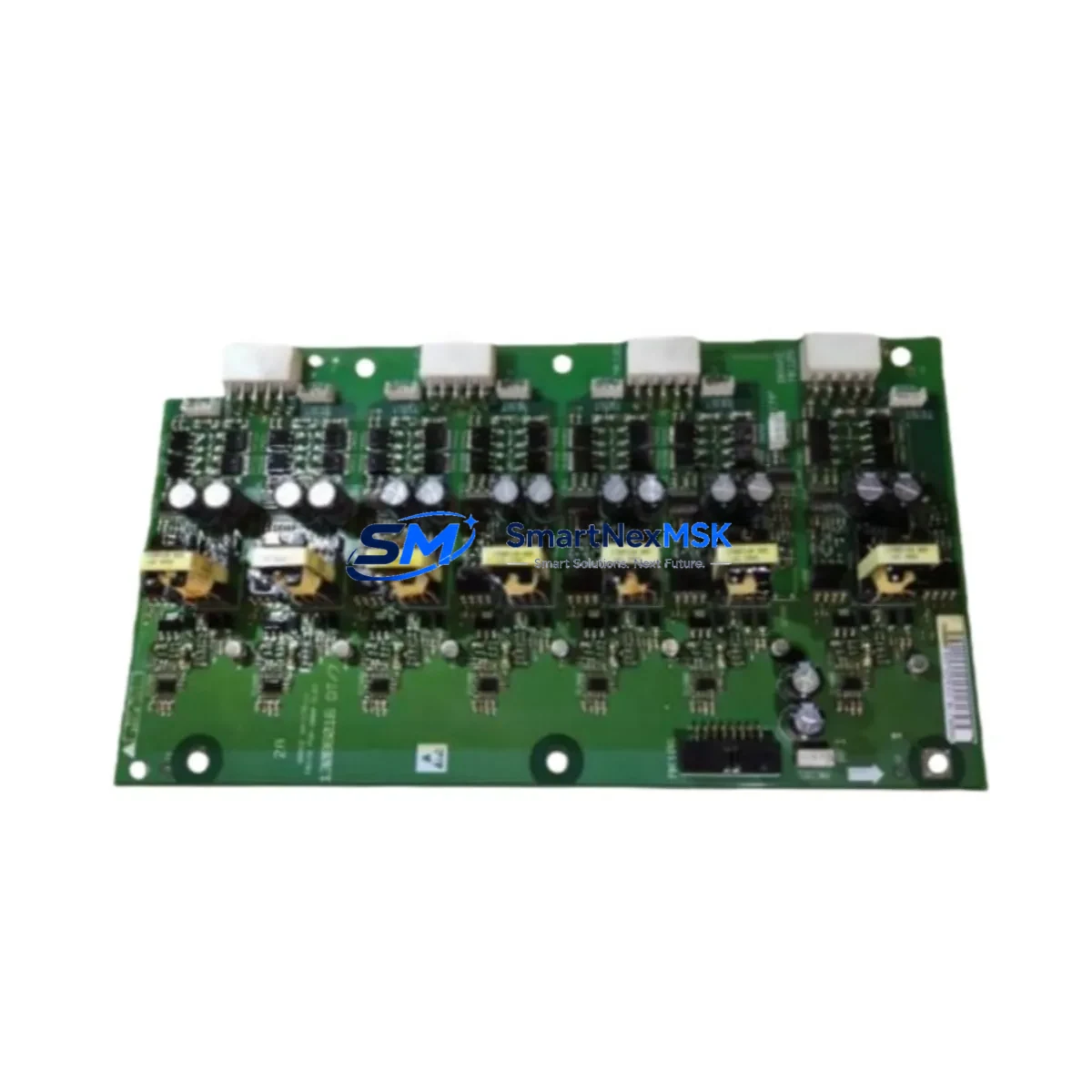
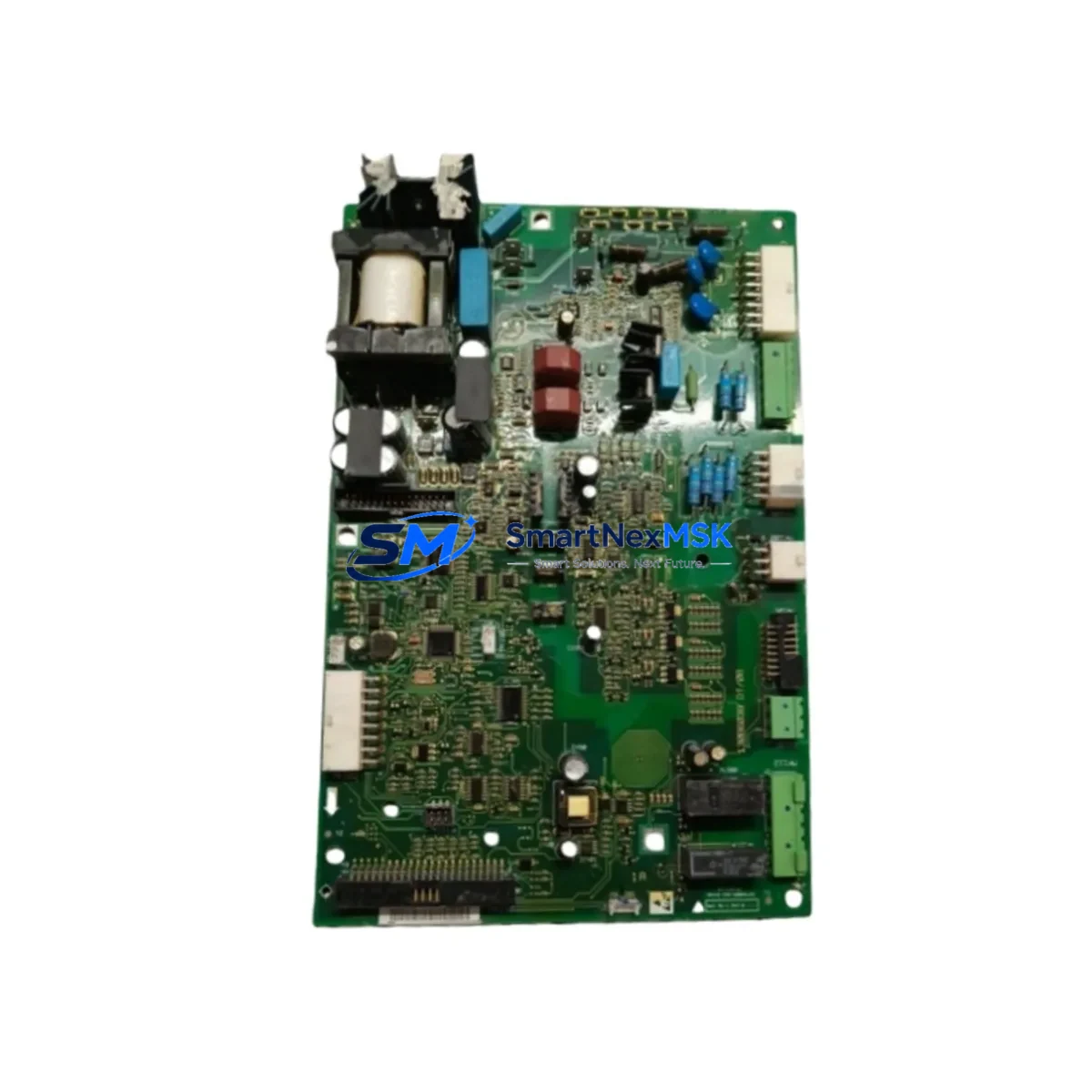
The Danfoss M8777/153-09-B615A2E1 is a factory-original VFD control board engineered for the VLT Series variable frequency drive platform — one of the most widely deployed drive families in industrial automation, HVAC, water treatment, and process control environments. When this control board fails, the entire drive becomes inoperable, causing unplanned downtime that can cascade across production lines, pump stations, or conveyor systems. Sourcing a verified replacement quickly is not optional — it is a core maintenance discipline.
At SMARTNEXMSK, this board is pre-inspected, function-tested, and dispatched with a 12-month warranty. Every unit is cross-referenced against the original Danfoss VLT bill of materials to confirm firmware compatibility, connector pinout integrity, and parameter retention capability. Whether you are executing a planned overhaul or responding to an emergency fault, this spare is ready to install.
Spare Maintenance Table
| Parameter | Specification |
|---|---|
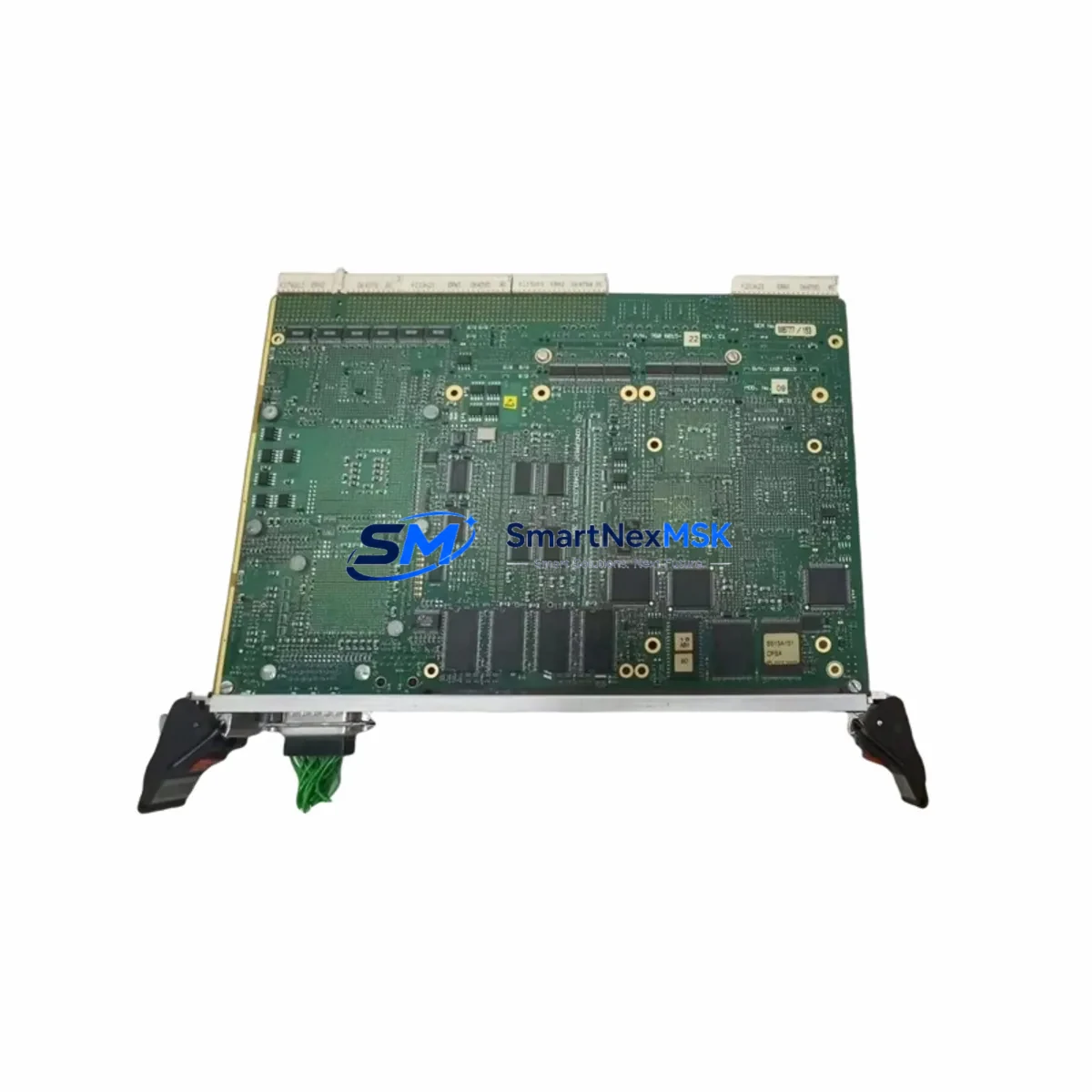
| Part Number | M8777/153-09-B615A2E1 |
| Brand | Danfoss |
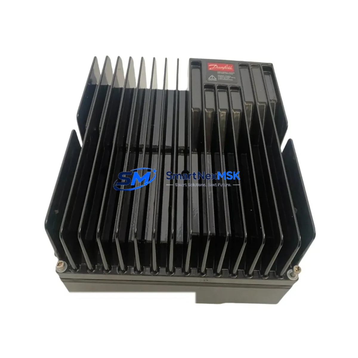
| Series | VLT (Variable Frequency Drive) |
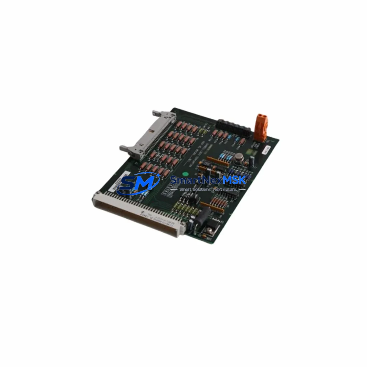
| Component Type | VFD Control Board |
| Origin | Denmark (DK) |
| Compatibility | Danfoss VLT Series drives; confirm frame size and firmware revision before installation |
| Mounting | Direct board replacement; follow OEM torque and ESD handling procedures |
| Application Environment | Industrial automation, HVAC, water/wastewater, process control, conveyor systems |
| Pre-Shipment Testing | Function-tested and inspected prior to dispatch |
| Warranty | 12 months from date of delivery |
| Condition | Original spare — new or fully refurbished to OEM specification |
| Lead Time | In-stock units ship within 1–3 business days |
Maintenance Planning for Continuous Operation
A VFD control board failure rarely occurs in isolation. Maintenance engineers performing a root-cause analysis after an M8777/153-09-B615A2E1 fault should treat the replacement as an opportunity to audit the entire drive cabinet and associated electrical circuit. Begin with the DC bus capacitor bank — capacitor degradation is a leading cause of control board stress and premature failure in aging VLT drives. Inspect the gate driver board and IGBT power module for signs of thermal damage or carbon tracking, as a shorted output stage can destroy a replacement control board within minutes of energisation if not identified first.
Check the 24 VDC internal power supply module that feeds the control logic; a sagging or noisy supply rail will cause erratic parameter behaviour and communication faults even after a board swap. Review the brake resistor and brake chopper circuit if the drive operates in regenerative or high-inertia applications — an unprotected overvoltage event is a common board killer. On the I/O side, verify all analog input signal conditioners and signal isolators connected to the drive’s reference and feedback terminals; a ground loop or floating signal can inject noise that corrupts the control board’s ADC inputs.
For networked drives, inspect the fieldbus communication module — whether PROFIBUS DP, DeviceNet, or Modbus RTU — and confirm that the network termination resistors are correctly installed. A communication module fault can be misdiagnosed as a control board failure. Similarly, check the LCP (Local Control Panel) keypad and its ribbon cable connector; a damaged keypad can prevent parameter upload after board replacement. If the drive is integrated into a PLC-controlled system, verify the digital I/O wiring to the PLC input card and confirm that the enable signal, fault reset, and speed reference signals are within specification before powering up the replacement board.
For cabinet-level maintenance, inspect the main contactor, input line reactor, EMC filter, and fuse block upstream of the drive. A blown input fuse or a failing contactor with high contact resistance can cause undervoltage faults that stress the new control board. Terminal blocks and cable ferrules should be re-torqued to specification during any planned board replacement. Document the drive’s parameter set before removal and restore it to the replacement board using the LCP copy function or a PC-based tool to avoid commissioning delays.
Site Replacement Workflow
Before removing the M8777/153-09-B615A2E1, isolate the drive from mains power and wait a minimum of 5 minutes for the DC bus to discharge below 50 VDC — verify with a calibrated multimeter before touching any internal components. Photograph the existing wiring and connector positions for reference. Remove the LCP panel, record all parameters if not already backed up, then carefully extract the control board by releasing the retention clips and disconnecting the ribbon and signal connectors in sequence.
Install the replacement board in reverse order, ensuring all connectors are fully seated and the ESD wrist strap is worn throughout. Restore the parameter set from backup. Power up the drive in local control mode first, verify the display initialises correctly, and check for any active fault codes before transferring to remote or automatic control. Confirm motor rotation direction and speed reference tracking before returning the drive to production. This structured workflow minimises re-energisation risk and reduces total downtime to under two hours for a trained technician.
For legacy VLT installations where the original firmware version is no longer available, SMARTNEXMSK can advise on compatible firmware alternatives and parameter migration strategies. Long-term supply continuity for the M8777/153-09-B615A2E1 and related VLT spare parts is maintained to support extended system life beyond OEM end-of-sale dates.
Spare Parts Support FAQ
Q: Is the M8777/153-09-B615A2E1 compatible with all VLT Series drives?
A: This control board is designed for specific VLT Series frame sizes and power ratings. Always cross-reference the drive’s nameplate data and existing board part number before ordering. Contact our technical team with your drive serial number for a confirmed compatibility check.
Q: What does the 12-month warranty cover?
A: The warranty covers manufacturing defects and functional failures under normal operating conditions for 12 months from the delivery date. It does not cover damage caused by incorrect installation, overvoltage events, or failure to follow OEM installation procedures. All warranty claims are supported with a replacement-first policy to minimise your downtime.
Q: How is the board tested before shipment?
A: Each unit undergoes a pre-shipment functional inspection covering power-up initialisation, communication interface response, and I/O signal integrity. Units that do not pass inspection are not dispatched. A test report is available on request for critical applications.
Q: Can you support ongoing spare parts inventory for our VLT fleet?
A: Yes. SMARTNEXMSK offers long-term supply agreements for industrial maintenance teams managing multiple VLT drives. We maintain buffer stock of high-demand VLT spare parts and can provide scheduled replenishment to support your planned maintenance calendar and emergency reserve requirements.
© 2026 SMARTNEXMSK. All rights reserved.
Original Source: https://smartnexmsk.com
Contact: sales@smartnexmsk.com | +86 18259474341