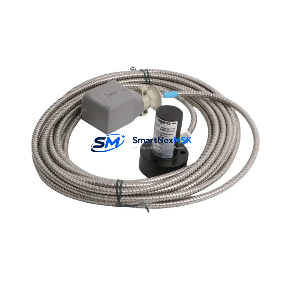
EPRO PR6423/10R-111 Spare for PR6423 Series Automation
The EPRO PR6423/10R-111 is an original eddy-current proximity transducer engineered for continuous shaft vibration and position monitoring in rotating machinery. Designed to API 670 standards, this spare is a direct maintenance replacement for aging or failed PR6423 series sensors deployed across turbine control panels, compressor trains, and critical DCS/PLC-integrated protection systems. For maintenance engineers managing unplanned downtime risk, stocking a verified PR6423/10R-111 spare is a fundamental element of any rotating equipment reliability program.
Whether you are executing a planned turnaround, responding to a vibration alarm, or conducting a routine control cabinet inspection, the PR6423/10R-111 delivers the dimensional and electrical compatibility required for a drop-in replacement without recalibration of the full measurement chain. Its 10 mm tip diameter and standardized cable termination ensure compatibility with existing EPRO CON021, CON041, and TK3 series signal conditioning modules already installed in your system.
Spare Maintenance Table
| Parameter | Specification |
|---|---|
| SKU / Part Number | PR6423/10R-111 |
| Brand | EPRO (Baker Hughes / Bently Nevada compatible ecosystem) |
| Series | PR6423 |
| Sensor Type | Eddy-Current Proximity Transducer |
| Tip Diameter | 10 mm |
| Sensitivity | 8 mV/µm (nominal) |
| Measurement Range | 0.25 mm – 2.25 mm (linear range) |
| Supply Voltage | -24 VDC (via signal conditioner) |
| Output Signal | DC voltage proportional to gap distance |
| Standard Compliance | API 670 (4th & 5th Edition) |
| Cable Length | Matched extension cable required (PR6423/010 or equivalent) |
| Operating Temperature | -35°C to +120°C |
| IP Rating | IP67 (connector end sealed) |
| Country of Origin | Germany |
| Compatibility | CON021, CON041, TK3 series signal conditioners; PR6423 series extension cables |
| Application | Shaft radial vibration, axial position, differential expansion monitoring |
| Warranty | 12 Months from date of shipment |
| Condition | Original, new-in-box or tested serviceable |
| Lead Time | In-stock: ships within 2 business days |
Maintenance Planning for Continuous Operation
When a PR6423/10R-111 proximity transducer is flagged for replacement during a vibration alarm investigation or scheduled outage, experienced maintenance engineers know that the sensor itself is rarely the only component requiring attention. A thorough inspection of the full measurement chain and associated control cabinet infrastructure is essential to prevent repeat failures and ensure the replacement sensor performs to specification from the moment it is commissioned.
Begin by verifying the PR6423/010 or PR6423/005 extension cable for continuity, insulation resistance, and connector integrity — a degraded cable is a common root cause of erratic vibration readings that are misdiagnosed as transducer failure. Next, inspect the paired CON021 or CON041 signal conditioner module for correct bias voltage output (typically -10.5 VDC to -12 VDC at the transducer tip gap), as a conditioner with drifted output will cause the replacement PR6423/10R-111 to read incorrectly even when the sensor itself is healthy.
Within the same control cabinet, check the 24 VDC power supply module feeding the vibration monitoring rack — voltage ripple or marginal regulation is a silent contributor to measurement noise. If the system uses a TK3 series rack or equivalent EPRO monitoring chassis, inspect the backplane connectors and card-edge contacts for oxidation or fretting corrosion, particularly in high-vibration environments. Loose or corroded backplane connections can introduce ground loops that corrupt the low-level DC output from the PR6423/10R-111.
For systems integrated into a DCS or safety instrumented system (SIS) via 4–20 mA transmitters or relay outputs, verify that the signal isolator or barrier module (such as a Zener barrier or galvanic isolator) is within calibration and has not developed leakage current that would offset the vibration channel. Simultaneously, confirm that the terminal block wiring in the junction box and marshalling cabinet is tight, correctly labeled, and free of moisture ingress — a common issue in outdoor or coastal installations.
If the machine protection system includes a relay output module or trip amplifier connected to the vibration channel, test the relay contact resistance and setpoint accuracy before returning the system to service. Finally, if an HMI or operator panel displays the vibration trend, verify that the engineering unit scaling and alarm setpoints are correctly configured after the transducer swap to avoid nuisance trips during the post-maintenance run-up.
Site Replacement Workflow
Step 1 — Isolation and Permit: Obtain a work permit and isolate the vibration monitoring channel at the DCS or protection system. Do not de-energize the full machine protection rack unless required — most PR6423 series transducers can be replaced with the monitoring system in bypass mode, minimizing exposure time.
Step 2 — Gap Measurement Before Removal: Record the existing air gap (typically 1.0 mm ± 0.1 mm for standard shaft targets) using a feeler gauge or the conditioner’s DC output voltage. This baseline confirms whether the original transducer had drifted from its calibrated position.
Step 3 — Transducer Removal: Unscrew the PR6423/10R-111 from its mounting bracket. Note the thread engagement depth and any locking compound used. Clean the mounting threads and inspect the bracket for cracks or deformation.
Step 4 — Replacement Installation: Install the new PR6423/10R-111, setting the air gap to the system-specified value (refer to the original commissioning record or OEM documentation). Apply thread-locking compound as specified. Reconnect the extension cable, ensuring the connector is fully seated and the locking ring is engaged.
Step 5 — Verification: With the conditioner energized, measure the DC output voltage at the conditioner output terminals. Confirm the voltage corresponds to the set gap distance using the 8 mV/µm sensitivity factor. Compare against the pre-removal baseline and the system’s acceptance band.
Step 6 — Return to Service: Remove the bypass, restore the monitoring channel, and observe the vibration trend on the HMI for a minimum of 15 minutes during machine run-up. Document the replacement in the maintenance management system with the new transducer serial number, gap setting, and conditioner output voltage.
This workflow is applicable to both planned outage replacements and emergency corrective maintenance scenarios, and is compatible with legacy PR6423 installations as well as newer EPRO system configurations.
Spare Parts Support FAQ
Q1: Is the PR6423/10R-111 a direct drop-in replacement for older PR6423 series variants?
Yes. The PR6423/10R-111 maintains dimensional, electrical, and connector compatibility with the broader PR6423 series family. It is designed to replace worn or failed units without requiring modification to the mounting bracket, extension cable, or signal conditioner, provided the existing infrastructure is within specification. Always verify the extension cable part number and conditioner model before installation to confirm system-level compatibility.
Q2: What is the recommended spare parts inventory strategy for PR6423/10R-111 in a rotating equipment fleet?
For facilities operating three or more machines equipped with PR6423 series transducers, maintaining a minimum of two PR6423/10R-111 units in the on-site spare parts store is recommended. Pair each transducer spare with a matched extension cable (PR6423/010 or PR6423/005) and a spare CON021 or CON041 conditioner module to enable a complete measurement chain replacement during an emergency. Annual stock review aligned with planned outage schedules prevents obsolescence and ensures spares remain within their storage life.
Q3: How is each PR6423/10R-111 unit tested before shipment?
Each unit undergoes electrical continuity verification, insulation resistance testing, and sensitivity confirmation against a reference target prior to dispatch. Units are shipped with a test report confirming the DC output voltage at a known gap distance. The 12-month warranty covers manufacturing defects and performance deviations from published specifications under normal operating conditions.
Q4: Can the PR6423/10R-111 be used in hazardous area (Ex) installations?
The PR6423/10R-111 is suitable for use in hazardous areas when installed in conjunction with an approved Zener barrier or galvanic isolator rated for the applicable zone classification. The transducer itself does not carry an intrinsic safety certification independently — the system-level Ex approval depends on the conditioner and barrier combination. Consult the EPRO system documentation and your local Ex certification authority before deploying in Zone 1 or Zone 2 classified areas.
© 2026 SMARTNEXMSK. All rights reserved.
Original Source: https://smartnexmsk.com
Contact: sales@smartnexmsk.com | +86 18259474341