FOXBORO FBM201 RH914SQ Maintenance-Ready Spare FBM200 Automation
The FOXBORO FBM201 RH914SQ is an original DCS interface module from the FBM200 Series, designed for use within Foxboro I/A Series distributed control systems. As a maintenance-ready spare, this module supports rapid field replacement, minimizing unplanned downtime in continuous process environments including oil & gas, chemical, power generation, and pulp & paper facilities. Each unit is sourced, inspected, and dispatched with full traceability to support your site’s spare parts inventory strategy and long-term system availability.
For maintenance engineers managing aging Foxboro I/A Series control cabinets, the FBM201 RH914SQ represents a critical line-replaceable unit (LRU). Its role in field bus communication and I/O signal conditioning makes it a high-priority spare in any preventive maintenance (PM) schedule. Procurement engineers will find this module available for immediate dispatch, backed by a 12-month warranty and pre-shipment functional verification.
Spare Maintenance Table
| Parameter | Specification |
|---|---|
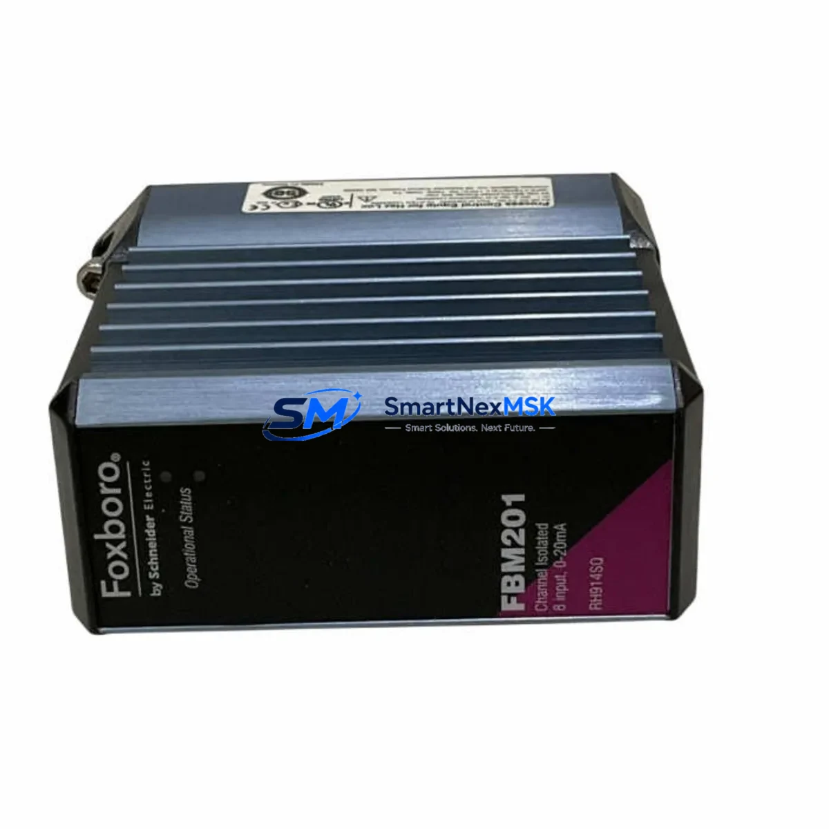
| Part Number | FBM201 / RH914SQ |
| Brand | FOXBORO (Schneider Electric) |
| Series | FBM200 / I/A Series DCS |
| Module Type | DCS Interface Module |
| Communication Protocol | Fieldbus / I/A Series proprietary bus |
| I/O Compatibility | FBM200 Series I/O subsystem |
| Mounting | DIN rail / baseplate carrier (FBM200 rack) |
| Operating Voltage | 24 VDC (nominal, via backplane) |
| Operating Temperature | 0°C to 60°C |
| Application Environment | Industrial process control, hazardous area compatible configurations |
| Origin | USA (Original FOXBORO manufacture) |
| Compatibility | Foxboro I/A Series DCS, FBM200 Series baseplate |
| Maintenance Role | Line-replaceable unit (LRU), hot-swap capable in supported configurations |
| Pre-Shipment Test | Functional verification performed before dispatch |
| Warranty | 12 Months |
Maintenance Planning for Continuous Operation
When scheduling replacement of the FBM201 RH914SQ during a planned shutdown or emergency callout, maintenance engineers should treat this module as part of a broader control loop inspection. The FBM201 interfaces directly with the FBM200 Series baseplate, so the baseplate connectors and backplane power rails should be inspected for oxidation or mechanical wear before installing the replacement module.
Power integrity is a common root cause of interface module failures. Before commissioning the new FBM201, verify the 24 VDC supply from the associated power supply module — such as the Foxboro FPS0810 or equivalent redundant power supply — is within tolerance. A degraded power supply can cause repeated module faults and shorten the service life of the replacement unit.
I/O signal integrity should also be confirmed. Check the field wiring terminations at the associated marshalling terminal blocks and I/O terminal assemblies. Loose or corroded terminals are a frequent cause of intermittent faults that are misdiagnosed as module failures. If the system uses HART-enabled field instruments, verify that the HART signal conditioners or HART multiplexers in the loop are functioning correctly, as signal noise can affect FBM communication stability.
For systems with redundant FBM configurations, inspect the companion FBM201 module and the redundancy cable connecting the primary and secondary modules. A failed redundancy link can leave the system operating in simplex mode without operator awareness, increasing risk during the next fault event.
Communication health should be validated at the Nodebus or Fieldbus level. If the plant uses a CP60 or CP270 control processor, review the processor’s diagnostic logs for any bus communication errors that preceded the module fault. In some cases, a failing FBM201 will generate upstream errors in the control processor before the module itself alarms.
Relay output modules and discrete I/O modules connected to the same I/O subsystem — such as FBM242 or FBM237 — should be included in the inspection round. A fault in one module can mask or trigger secondary faults in adjacent modules sharing the same baseplate segment. Signal isolators installed between the FBM and field devices should also be checked for drift or failure, particularly in high-temperature or high-humidity environments.
For facilities maintaining a minimum spare parts inventory, it is recommended to hold at least one FBM201 RH914SQ alongside related spares including the FBM200 baseplate, redundant power supply modules, and communication interface cables. This ensures that a complete control loop can be restored within a single maintenance window, regardless of which component has failed.
Site Replacement Workflow
Step 1 — Preparation: Obtain the replacement FBM201 RH914SQ and confirm the part number and revision level match the installed unit. Review the system’s I/A Series configuration database to identify the module’s tag assignments and I/O channel mapping before removal.
Step 2 — Safe Isolation: Follow site lock-out/tag-out (LOTO) procedures. If the system supports hot-swap replacement in the installed configuration, coordinate with the control room operator to place the affected control loops in manual mode before extraction. For non-redundant configurations, a brief process interruption may be required.
Step 3 — Module Extraction: Release the module locking mechanism on the FBM200 baseplate and extract the FBM201 carefully. Inspect the baseplate connector pins for damage or contamination. Clean with appropriate contact cleaner if required.
Step 4 — Installation: Insert the replacement FBM201 RH914SQ firmly into the baseplate slot until the locking mechanism engages. Verify the module’s status LEDs indicate correct initialization. The I/A Series system should automatically download the module configuration from the control processor.
Step 5 — Verification: Confirm all I/O channels are communicating correctly via the system’s diagnostic display or engineering workstation. Return affected control loops to automatic mode and monitor for a minimum of 15 minutes to confirm stable operation.
Step 6 — Documentation: Record the replacement in the site maintenance management system (CMMS), including the removed module’s serial number, installation date of the replacement, and any observations noted during the procedure. Return the removed module for evaluation or disposal per site procedures.
Spare Parts Support FAQ
Q1: Is the FBM201 RH914SQ an original FOXBORO module or a third-party replacement?
This is an original FOXBORO FBM201 RH914SQ module, manufactured to Foxboro’s original specifications. It is not a third-party clone or aftermarket substitute. Each unit is verified against the original part number and revision before dispatch.
Q2: How is the module tested before shipment?
Every FBM201 RH914SQ undergoes functional verification prior to dispatch. This includes power-on testing, communication interface checks, and visual inspection of connectors and housing. A test report is available upon request for critical applications.
Q3: What is the warranty coverage and what does it include?
All units are covered by a 12-month warranty from the date of shipment. The warranty covers manufacturing defects and functional failures under normal operating conditions. Warranty claims are supported with direct technical assistance and expedited replacement dispatch to minimize site downtime.
Q4: Can this module replace an older FBM201 revision installed in an existing I/A Series system?
In most cases, yes. The FBM201 RH914SQ is designed for backward compatibility within the FBM200 Series baseplate ecosystem. However, it is recommended to verify the installed system’s software revision and configuration database compatibility before installation. Our technical team can assist with compatibility confirmation prior to purchase.
© 2026 SMARTNEXMSK. All rights reserved.
Original Source: https://smartnexmsk.com
Contact: sales@smartnexmsk.com | +86 18259474341