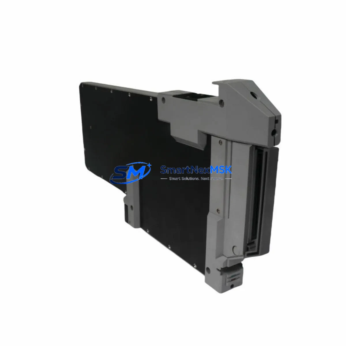
Foxboro FBM204 Retrofit-Ready I/O Module for I/A Series Control Systems
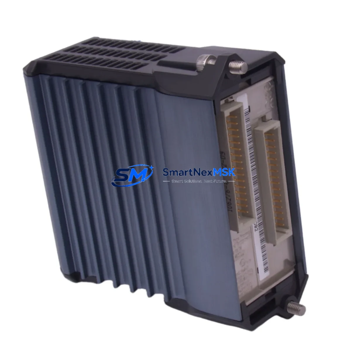
The Foxboro FBM204 is a high-density analog input/output module engineered for the Foxboro I/A Series Distributed Control System (DCS). As legacy I/A Series installations age and OEM support windows close, the FBM204 has become one of the most sought-after retrofit components for plants seeking to extend the operational life of their existing control infrastructure without committing to a full platform migration. Whether you are replacing a failed unit, building a critical spare inventory, or executing a phased modernization of your control cabinets, the FBM204 delivers the electrical and functional compatibility your engineering team requires.
Our stock of FBM204 modules is sourced, inspected, and tested prior to shipment. Each unit undergoes bench verification of channel integrity, backplane communication, and signal conditioning accuracy before it leaves our facility. A 12-month warranty is included with every shipment, covering functional defects under normal operating conditions.
Upgrade Compatibility Table
| Parameter | FBM204 Specification | Retrofit Notes |
|---|---|---|
| Module Type | Analog I/O (Multi-channel) | Direct slot replacement in I/A Series baseplate |
| Backplane Interface | I/A Series FBM Baseplate (P0914YE / P0914YF compatible) | Verify baseplate revision before installation |
| Communication Protocol | Nodebus / Fieldbus (I/A Series native) | No protocol converter required for same-platform swap |
| Power Supply Compatibility | 24 VDC via backplane | Confirm CP60 or CP30 power supply capacity before adding modules |
| Terminal Wiring | Field termination via FBM terminal assembly (FTA) | Retain existing FTA wiring; no re-termination required for like-for-like swap |
| Module Address | Configured via I/A Series System Definition (SD) files | Restore SD file and compound blocks; verify letterbug assignment |
| HMI / Display Compatibility | Compatible with FoxView, FoxDraw, and third-party SCADA via OPC | No HMI screen rebuild required for direct replacement |
| Replacement Scope | Drop-in for failed or end-of-life FBM204 units | Suitable for like-for-like swap or controlled upgrade path |
| Commissioning Requirement | SD file restore + loop calibration check | Typically completed within 2–4 hours per module |
| Warranty | 12 Months | Covers functional defects under normal operating conditions |
Retrofit Planning for Existing Automation Systems
Successful FBM204 integration into an aging I/A Series installation requires a structured pre-replacement audit. Before pulling the failed module, your team should document the current letterbug address and confirm the associated compound and block structure in the Foxboro Control Processor (CP60 or CP30). The CP60 manages module polling and must have sufficient processing headroom to accommodate the restored I/O point list without cycle time degradation.
Field termination is handled through the Foxboro FTA (Field Termination Assembly) — typically a dedicated FTA model matched to the FBM204’s signal type. In most retrofit scenarios, the FTA remains in place and the FBM module is hot-swapped or cold-swapped depending on plant safety procedures. If the FTA itself shows signs of corrosion or terminal fatigue, concurrent replacement with a new FTA assembly is recommended to avoid intermittent signal faults post-commissioning.
Plants running mixed I/A Series generations often have a combination of FBM201, FBM202, FBM203, and FBM207 modules installed across multiple baseplates. When planning a rack-level upgrade, it is advisable to audit all FBM slots simultaneously and identify modules approaching end-of-life. The P0914YE baseplate accommodates up to 16 FBM modules and is the most common carrier in I/A Series control cabinets. Ensure the baseplate’s backplane connectors are clean and undamaged before seating the replacement FBM204.
For installations that include Foxboro FCP270 or FCM10E fieldbus communication modules, verify that the Fieldbus segment load budget is not exceeded after the module swap. The FBM204 draws a defined current from the Nodebus segment, and adding replacement modules to a heavily loaded segment without recalculating the power budget can cause intermittent communication faults. The Foxboro 200 Series Power Supply (P0922VW) or equivalent should be checked for available current margin before proceeding.
If your retrofit scope extends to the control room, confirm that FoxView workstation display faceplates and alarm configurations reference the correct module tag names. In most like-for-like FBM204 replacements, no HMI rework is required. However, if the replacement is part of a broader I/O consolidation — for example, migrating from multiple single-function FBMs to a multi-channel FBM204 — the associated FoxDraw graphics and OPC tag mappings will need to be updated before returning the loop to automatic control.
Programming cable access is required if the CP60 or CP30 needs a compound reload. The Foxboro AW70 Application Workstation running I/A Series System software is the standard engineering tool for SD file management, compound download, and loop tuning. Ensure the AW70 is connected and the correct system database version is loaded before initiating the module replacement sequence.
Downtime Control During System Migration
Minimizing unplanned downtime during an FBM204 swap requires preparation at three levels: documentation, spare parts staging, and a clear step-by-step execution plan agreed upon by operations and maintenance before the maintenance window opens.
Begin by exporting the current compound and block configuration from the CP60 or CP30 to a backup file on the AW70. This ensures that if the SD file restore encounters an error, the original logic can be reloaded without delay. Tag the field cables at the FTA before disconnecting anything — even if the wiring appears clearly labeled, physical tags eliminate the risk of mis-termination during a time-pressured swap.
For critical control loops — flow, pressure, or temperature loops feeding safety interlocks — coordinate with the control room to place the affected loops in manual mode before pulling the FBM204. This preserves the last known output value at the final control element and prevents process upsets caused by a loss-of-signal condition during the module exchange. Once the replacement FBM204 is seated and the SD file is restored, perform a channel-by-channel signal verification against the loop calibration records before returning each loop to automatic.
In multi-module retrofit projects, stagger the replacement sequence to avoid taking down more than one control loop at a time. This approach keeps the process running at reduced automation coverage rather than risking a full section shutdown. With proper preparation, a single FBM204 replacement can typically be completed within a 2–4 hour maintenance window, including signal verification and loop return-to-auto confirmation.
All modules supplied by SMARTNEXMSK are pre-tested and shipped with a test report. This eliminates the risk of installing a defective unit and discovering the fault only after the maintenance window has closed — a scenario that can extend unplanned downtime significantly. Our 12-month warranty provides additional assurance that the replacement module will perform reliably throughout the post-retrofit stabilization period.
Retrofit Support FAQ
Q1: Is the FBM204 a direct drop-in replacement for a failed unit in my I/A Series rack?
Yes. The FBM204 is designed for direct slot replacement in the I/A Series FBM baseplate. No hardware modification is required. After seating the module, restore the SD file from your AW70 backup, verify the letterbug assignment, and perform a loop calibration check before returning to automatic control.
Q2: What wiring changes are needed at the field termination assembly?
For a like-for-like FBM204 replacement, no wiring changes are required at the FTA. The existing field cable terminations remain in place. If you are consolidating I/O from an older single-channel FBM to the FBM204’s multi-channel architecture, a wiring remap at the FTA will be necessary — contact our technical team for a pre-project wiring review.
Q3: How do I verify communication compatibility with my existing Nodebus or Fieldbus segment?
Confirm the FBM204’s Nodebus address matches the letterbug configured in your SD file. Use the I/A Series diagnostic tools on the AW70 to verify module recognition on the Nodebus segment after installation. If the module does not appear, check the backplane connector seating and the CP60 polling configuration before escalating to a segment-level fault diagnosis.
Q4: What does the 12-month warranty cover, and what is the process for a warranty claim?
The 12-month warranty covers functional defects in the FBM204 module under normal operating conditions, including channel failure, backplane communication faults, and signal conditioning errors. Physical damage caused by incorrect installation, overvoltage, or environmental factors is excluded. To initiate a warranty claim, contact sales@smartnexmsk.com with your order number, a description of the fault, and any available diagnostic logs from the AW70.
© 2026 SMARTNEXMSK. All rights reserved.
Original Source: https://smartnexmsk.com
Contact: sales@smartnexmsk.com | +86 18259474341