Foxboro FBM207B P0914WH Spare for I/A Series Automation: Spare Replacement & Industrial Downtime Risk Control
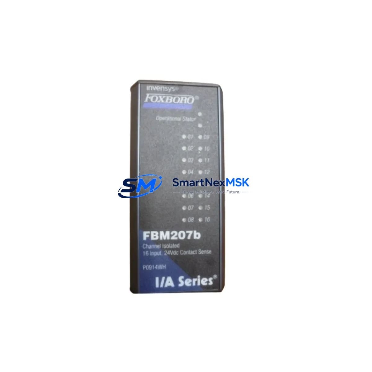
The Foxboro FBM207B (part number P0914WH) is a 16-channel isolated analog input Field Bus Module designed for the Foxboro I/A Series Distributed Control System (DCS). As a critical signal acquisition component within the I/A Series architecture, this module handles 4–20 mA and voltage input signals from field transmitters, converting them into digital process values for the control processor. When this module fails or degrades, the consequences extend beyond a single loop — entire process trains can lose visibility, triggering unplanned shutdowns in refining, chemical, power generation, and water treatment facilities.
Maintaining a verified spare FBM207B P0914WH in your site inventory is one of the most cost-effective strategies for protecting continuous operation. With lead times for new DCS hardware often stretching 8–20 weeks, a pre-tested, shelf-ready replacement module eliminates the most dangerous variable in emergency maintenance: procurement delay. Our FBM207B P0914WH units are sourced as original Foxboro hardware, inspected prior to dispatch, and backed by a 12-month warranty covering functional performance under normal operating conditions.
Spare Maintenance Table
| Parameter | Specification |
|---|---|
| Part Number | FBM207B / P0914WH |
| Brand | Foxboro (Schneider Electric) |
| Series | I/A Series DCS |
| Module Type | 16-Channel Isolated Analog Input FBM |
| Input Signal | 4–20 mA / 1–5 VDC (field-selectable per channel) |
| Channel Isolation | Channel-to-channel and channel-to-bus isolation |
| Communication Bus | Nodebus / Fieldbus Module Bus (I/A Series) |
| Mounting | I/A Series FBM Baseplate (compatible with standard I/A enclosures) |
| Power Supply | Supplied via baseplate from I/A Series power distribution |
| Operating Temperature | 0°C to 60°C (32°F to 140°F) |
| Humidity | 5% to 95% RH, non-condensing |
| Approvals | CE, UL (refer to original Foxboro documentation) |
| Compatibility | I/A Series DCS — FBM baseplate, CP60, CP30, CP40B processors |
| Maintenance Recommendation | Inspect annually; replace on first sign of channel drift or communication fault |
| Warranty | 12 Months — functional performance guarantee |
| Condition | Original Foxboro hardware, pre-shipment tested |
| Origin | USA |
Maintenance Planning for Continuous Operation
When a maintenance or reliability engineer schedules a planned inspection or responds to an FBM207B fault alarm, the replacement of this analog input module should never be treated in isolation. The FBM207B P0914WH sits within a broader signal chain and power distribution architecture — and a thorough site replacement workflow demands that adjacent components be verified simultaneously to prevent repeat failures and ensure loop integrity after the module is swapped.
Begin with the FBM baseplate itself: connector pins corrode over time, and a degraded baseplate can cause intermittent communication faults that mimic FBM hardware failure. Inspect the baseplate contacts and, if the system has been in service for more than 10 years, consider stocking a spare baseplate alongside the FBM207B. Next, verify the I/A Series power supply modules — typically the FPS (Field Power Supply) units — that feed the FBM enclosure. Voltage sag or ripple from an aging power supply can cause analog input drift across all channels, a symptom often misattributed to the FBM itself.
On the field side, inspect the terminal blocks and marshalling panels connecting field transmitters to the FBM207B input channels. Loose terminations, corroded lugs, or undersized conductors introduce resistance that shifts 4–20 mA readings. If the plant uses signal isolators or signal conditioners between field devices and the FBM, these should be tested for output accuracy — a failing isolator will corrupt the analog signal before it even reaches the module.
For systems where the FBM207B monitors critical process variables such as pressure, temperature, or flow, also verify the associated field transmitters (e.g., Foxboro IDP10, IGP10, or equivalent HART-capable transmitters) for calibration drift. A module replacement without transmitter verification can result in a clean module reporting inaccurate process values — a dangerous condition in safety-critical loops.
At the control processor level, confirm that the CP60 or CP40B control processor has correctly re-recognized the replaced FBM207B after installation. In some I/A Series configurations, the processor must be prompted to re-scan the Nodebus after a module swap. Check the Nodebus termination resistors and cable integrity if communication faults persist after replacement. Additionally, review the FBM communication cables (Nodebus coaxial or twisted-pair segments) for damage, especially in high-vibration or high-temperature environments.
If the plant control cabinet also houses FBM237 or FBM242 digital output modules, or FBM220 HART analog output modules, include these in the inspection round — they share the same power distribution and bus infrastructure and are subject to the same environmental stressors. Finally, for sites running aging I/A Series systems beyond their original design life, consider a broader lifecycle assessment that includes the Nodebus interface cards, redundant processor pairs, and any legacy FBM10 or FBM11 analog input modules still in service alongside the FBM207B.
Site Replacement Workflow
Step 1 — Pre-replacement verification: Confirm the fault is isolated to the FBM207B by checking the I/A Series system diagnostic display for module-specific fault codes. Document which channels are affected and whether the fault is communication-based or signal-quality-based.
Step 2 — Safe isolation: Place affected control loops in manual mode at the DCS operator station before removing the module. Notify operations personnel of the planned maintenance window. For safety-instrumented loops, coordinate with the SIS engineer before proceeding.
Step 3 — Module removal and inspection: Remove the FBM207B from the baseplate. Inspect the baseplate connector for corrosion, bent pins, or debris. Clean with appropriate contact cleaner if required. Record the module’s firmware revision label for compatibility verification.
Step 4 — Spare installation: Insert the replacement FBM207B P0914WH into the baseplate. The I/A Series architecture supports hot-swap in most configurations — verify this against your site’s specific system revision and safety procedures. Confirm the module LED status indicates normal operation (typically a steady green RUN indicator).
Step 5 — Loop verification: Return loops to automatic mode one at a time. Verify that all 16 channels are reading correctly against known field transmitter values. Use the I/A Series Integrated Control Configurator (ICC) or equivalent engineering workstation tool to confirm channel configuration has been retained.
Step 6 — Documentation: Update the site maintenance log with the replacement date, module serial number, and post-replacement loop test results. Flag the removed module for bench testing or return-to-vendor evaluation.
Spare Parts Support FAQ
Q1: Is the FBM207B P0914WH compatible with all I/A Series DCS revisions?
The FBM207B P0914WH is designed for the Foxboro I/A Series DCS platform and is compatible with standard FBM baseplates used across I/A Series generations. Compatibility with specific control processor revisions (CP30, CP40B, CP60) should be confirmed against your site’s system software version. We recommend providing your system revision details when ordering to allow pre-shipment compatibility verification.
Q2: How are units tested before shipment?
Each FBM207B P0914WH unit undergoes functional inspection prior to dispatch, including visual inspection, connector integrity check, and power-on verification where test infrastructure permits. Units are packaged in anti-static protective packaging with physical protection for transport. A 12-month warranty covers functional performance from the date of receipt.
Q3: What is the recommended spare inventory strategy for the FBM207B?
For plants with 10 or more FBM207B modules installed, maintaining a minimum of 1–2 verified spare units on-site is recommended. Given the extended lead times for new DCS hardware procurement (often 12–20 weeks for legacy Foxboro modules), a shelf-ready spare eliminates the primary risk factor in emergency maintenance scenarios. For critical process units with no redundancy on affected loops, a 1:5 spare ratio is a common industry benchmark.
Q4: Can the FBM207B P0914WH replace older FBM207 variants?
The FBM207B is an enhanced revision of the FBM207 family. In most I/A Series installations, the FBM207B P0914WH is a direct functional replacement for earlier FBM207 variants, subject to baseplate and system software compatibility. If your site is running an earlier I/A Series software revision, contact us with your system details for a compatibility assessment before ordering.
© 2026 SMARTNEXMSK. All rights reserved.
Original Source: https://smartnexmsk.com
Contact: sales@smartnexmsk.com | +86 18259474341