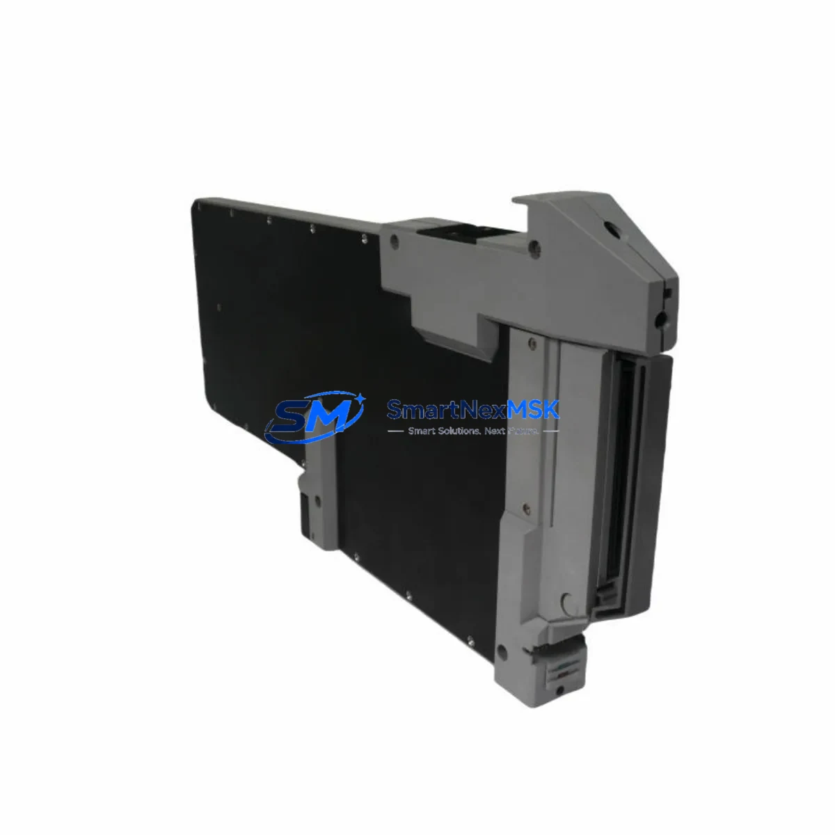
Foxboro FBM214 P0922VT Retrofit-Ready Nodebus Interface for I/A Series Control Systems
The Foxboro FBM214 P0922VT is a Nodebus Interface Module engineered for the Foxboro I/A Series Distributed Control System (DCS). As legacy I/A Series installations approach end-of-life or require capacity expansion, the FBM214 P0922VT serves as a direct retrofit replacement for discontinued Nodebus interface hardware, enabling plant engineers to restore full Nodebus communication without modifying existing rack wiring, backplane connectors, or control logic. Whether you are recovering from an unplanned module failure, executing a planned control system upgrade, or expanding I/O capacity on an aging control cabinet, the FBM214 P0922VT provides a verified, drop-in compatible solution backed by a 12-month warranty and pre-shipment functional testing.
In retrofit projects involving the I/A Series platform, the FBM214 P0922VT typically operates alongside a range of companion modules. Engineers frequently pair it with the FBM201 and FBM202 analog input modules when consolidating field wiring during a panel upgrade, and with the FBM207 and FBM211 digital I/O modules when migrating discrete control loops from older Foxboro SPEC 200 or SPEC 200 Micro systems. The module installs directly into the standard I/A Series FBM Enclosure (P0914YA or equivalent), sharing the same 24 VDC power rail supplied by the FPS0810 or FPS1620 field power supply. No additional power conditioning is required in most retrofit scenarios.
For sites transitioning from older Nodebus topologies, the FBM214 P0922VT maintains full compatibility with the Nodebus coaxial cable infrastructure already in place, eliminating the need to re-pull field cables — one of the most time-consuming and costly elements of a DCS migration. The module communicates with the CP60 or CP270 control processor via the standard I/A Series Nodebus protocol, and its module address is configured through the existing Foxboro Control Configurator or I/A Series System Manager software without requiring firmware changes or special licensing.
Upgrade Compatibility Table
| Parameter | Detail |
|---|---|
| Module SKU | FBM214 / P0922VT |
| Compatible Series | Foxboro I/A Series DCS |
| Interface Type | Nodebus Interface Module |
| Backplane Compatibility | Standard I/A Series FBM Enclosure (P0914YA and equivalents) |
| Communication Protocol | Foxboro Nodebus (coaxial, proprietary) |
| Compatible Controllers | CP60, CP270, CP40B and I/A Series control processors |
| Power Supply Requirement | 24 VDC via FPS0810 / FPS1620 field power supply |
| Installation Type | Direct drop-in replacement — no rack modification required |
| Address Configuration | Via Foxboro Control Configurator / I/A Series System Manager |
| Replaces / Supersedes | Discontinued FBM214 variants; legacy Nodebus interface cards |
| Retrofit Recommendation | Verify Nodebus segment address and cable termination before installation |
| Commissioning Notes | Confirm CP processor firmware version supports FBM214 module type |
| Warranty | 12-Month Warranty — covers manufacturing defects and functional failure |
| Pre-Shipment Testing | Full functional test performed before dispatch |
| Origin | China (CN) |
Retrofit Planning for Existing Automation Systems
A successful FBM214 P0922VT retrofit begins well before the module arrives on site. During the planning phase, engineers should audit the existing Nodebus segment layout, confirm the number of FBM stations on each segment, and verify that the replacement module’s Nodebus address does not conflict with active stations. In multi-enclosure installations, the FBM Enclosure baseplate and backplane connectors should be inspected for corrosion or mechanical wear — particularly in high-humidity or coastal environments where I/A Series cabinets have been in service for 15 or more years.
Power budget verification is equally critical. The FPS0810 field power supply supports up to 8 amps at 24 VDC, while the FPS1620 supports 16 amps. When adding the FBM214 P0922VT to an existing rack that already hosts FBM201 analog input modules, FBM207 digital output modules, and FBM211 pulse input modules, engineers must confirm that the aggregate current draw does not exceed the supply rating. Overloading the field power supply is a common cause of intermittent Nodebus communication faults that are frequently misdiagnosed as module failures.
Terminal wiring for the Nodebus coaxial connection should be inspected and re-terminated if the existing cable shows signs of impedance mismatch or physical damage. The Nodebus segment must be properly terminated at both ends with 75-ohm termination resistors; missing or degraded termination is a leading cause of communication errors after module replacement. If the site is also upgrading the HMI layer — for example, migrating from an older Foxboro Workstation to a modern SCADA platform — the FBM214 P0922VT’s Nodebus data is fully accessible through the I/A Series AIM historian and OPC DA/UA server, allowing HMI screen updates to proceed in parallel with the hardware retrofit without interrupting live process data.
For projects that include communication protocol migration — such as moving from legacy Nodebus to Ethernet-based FoxNet or integrating with a Modbus TCP supervisory layer — the FBM214 P0922VT can coexist with FBM242 Modbus interface modules and FBM237 HART multiplexer modules within the same enclosure, providing a phased migration path that avoids a full system cutover. Programming cable connections to the CP60 or CP270 processor via the standard RS-232 or Ethernet service port remain unchanged during the FBM214 swap, allowing engineers to monitor live diagnostics throughout the replacement procedure.
Downtime Control During System Migration
Minimizing unplanned downtime is the primary concern for any I/A Series retrofit involving Nodebus interface modules. The FBM214 P0922VT supports a structured hot-swap procedure when the control processor is placed in a controlled hold state: the operator first transfers affected control loops to manual mode at the DCS console, confirms that all downstream actuators are in a safe position, and then proceeds with the physical module swap. Because the FBM214 P0922VT is a direct drop-in replacement, the Nodebus address and module configuration are retained in the CP processor’s database — no re-download of the control strategy is required in most cases, provided the replacement module is of the same type and revision.
To further protect original program logic, engineers should export a full backup of the I/A Series control database using the Foxboro System Manager before beginning any hardware work. This backup preserves all function block configurations, loop tuning parameters, alarm setpoints, and Nodebus address assignments. If the replacement procedure requires a CP processor restart, the control strategy reloads automatically from the resident database, and Nodebus communication with the FBM214 P0922VT is re-established within the normal module initialization window — typically under 60 seconds for a healthy Nodebus segment.
For sites where continuous process operation is mandatory, a parallel commissioning approach is recommended: install and address the replacement FBM214 P0922VT in an adjacent spare slot, verify Nodebus communication and I/O channel mapping in the System Manager, and then perform the final cutover during a scheduled low-production window. This approach reduces the active cutover window to under 10 minutes and eliminates the risk of extended downtime caused by unexpected configuration issues. All pre-shipment functional testing results for the FBM214 P0922VT are documented and available upon request, supporting your site’s change management and MOC (Management of Change) process.
Retrofit Support FAQ
Q1: Is the FBM214 P0922VT a direct replacement for my existing Nodebus interface module?
Yes. The FBM214 P0922VT is designed as a drop-in replacement for the same SKU and compatible Nodebus interface variants used in the Foxboro I/A Series DCS. It installs into the standard FBM Enclosure without rack modification, and the Nodebus address is retained from the existing CP processor database. We recommend confirming the module revision level with your I/A Series System Manager before installation to ensure full compatibility with your CP firmware version.
Q2: What commissioning steps are required after installing the FBM214 P0922VT?
After physical installation, verify that the Nodebus segment address is correctly assigned in the Foxboro Control Configurator or System Manager. Confirm that the module appears online in the I/A Series diagnostic display and that all associated FBM I/O modules on the same Nodebus segment are communicating normally. Check Nodebus cable termination at both segment ends and inspect the 24 VDC power rail voltage at the FBM Enclosure backplane. No firmware download is required for a like-for-like replacement.
Q3: How do I verify wiring and terminal compatibility before installation?
The FBM214 P0922VT uses the standard I/A Series backplane connector and Nodebus coaxial interface — no field terminal rewiring is required. Before installation, inspect the backplane connector pins for damage or oxidation, and verify that the Nodebus coaxial cable is properly seated and terminated. If the site uses a field termination assembly (FTA) for signal wiring to associated FBM I/O modules, confirm that the FTA model is compatible with the FBM214’s I/O channel configuration as documented in the Foxboro FBM214 hardware manual.
Q4: What does the 12-month warranty cover, and is pre-shipment testing included?
Every FBM214 P0922VT unit undergoes full functional testing prior to shipment, verifying Nodebus communication, power consumption, and I/O channel integrity. The 12-month warranty covers manufacturing defects and functional failures under normal operating conditions. Warranty claims are supported with replacement or repair at no additional cost. Test reports are available upon request to support your incoming inspection and MOC documentation requirements.
© 2026 SMARTNEXMSK. All rights reserved.
Original Source: https://smartnexmsk.com
Contact: sales@smartnexmsk.com | +86 18259474341