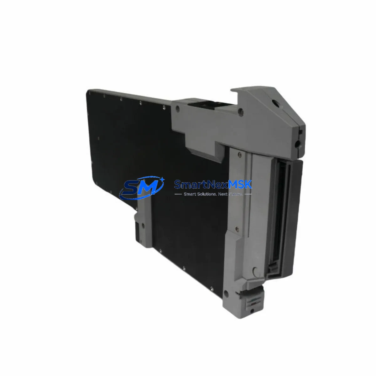
FOXBORO FBM215-P0922VU Maintenance-Ready Spare for I/A Series Automation
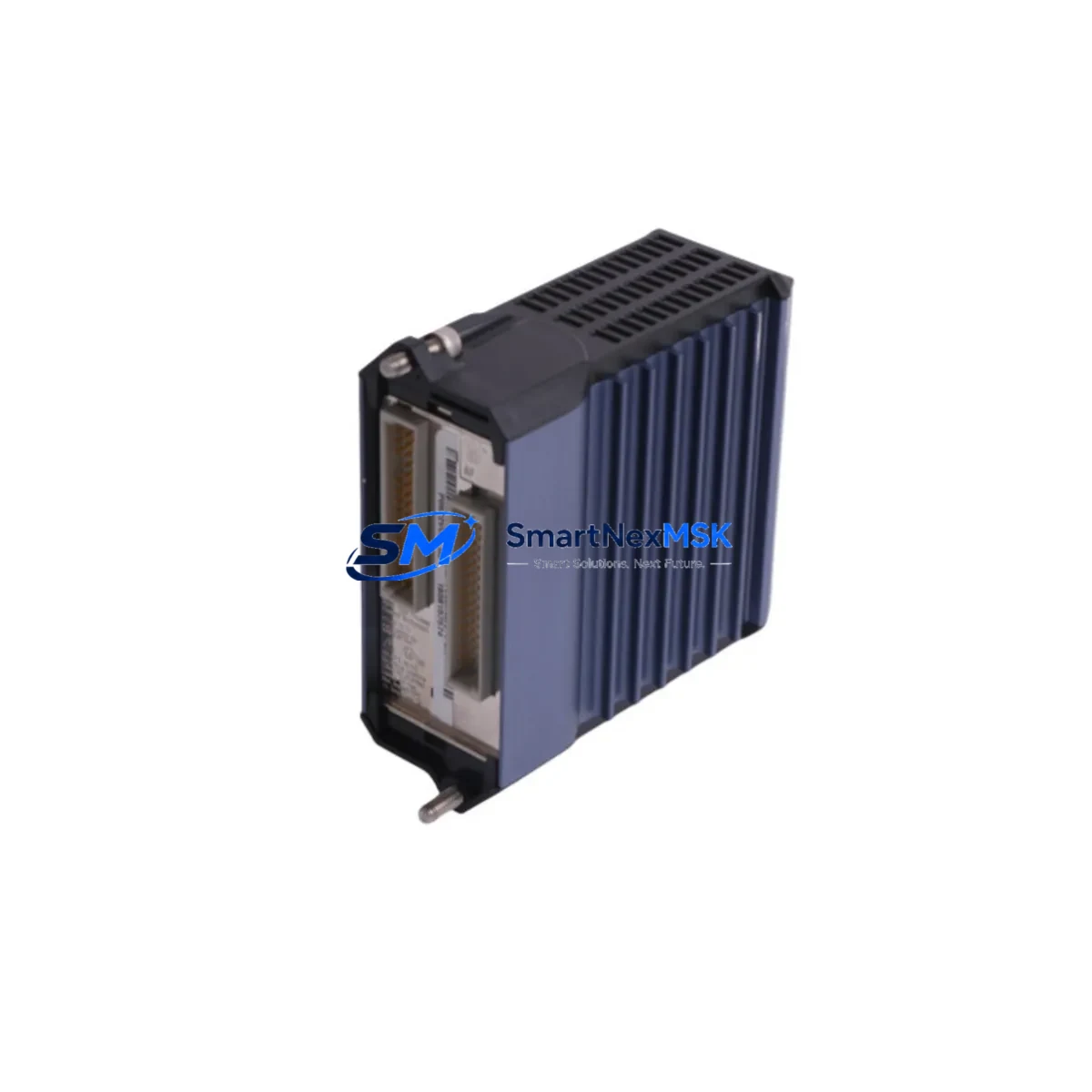
The FOXBORO FBM215-P0922VU is an original Fieldbus Module (FBM) designed for the Foxboro I/A Series Distributed Control System (DCS). As a critical I/O interface between field instruments and the control processor, this module plays a central role in process measurement, signal conditioning, and real-time data acquisition across continuous and batch manufacturing environments. Maintaining a verified spare of the FBM215-P0922VU in your parts inventory is one of the most effective strategies for reducing unplanned downtime and protecting process continuity in aging I/A Series installations.
For maintenance engineers managing legacy DCS infrastructure, the FBM215-P0922VU represents a direct, drop-in replacement that preserves existing wiring, configuration, and fieldbus addressing without requiring system re-engineering. Its compatibility with the I/A Series baseplate and FBM carrier architecture means that field replacement can be completed within a single maintenance window, minimizing the impact on production schedules.
Spare Maintenance Table
| Parameter | Specification |
|---|---|
| Part Number | FBM215-P0922VU |
| Brand | FOXBORO (Schneider Electric) |
| Series | I/A Series DCS |
| Module Type | Fieldbus I/O Module (FBM) |
| Function | Analog/Digital I/O Signal Interface, Fieldbus Communication |
| Compatibility | FOXBORO I/A Series DCS — FBM Carrier, Baseplate, CP60/CP270/CP40B Processors |
| Installation | Direct plug-in to FBM carrier; no tools required for module swap |
| Operating Environment | Industrial control room / marshalling cabinet; 0–60°C, humidity ≤95% non-condensing |
| Power Supply | Supplied via FBM carrier backplane (24 VDC typical) |
| Condition | Original, new or fully tested refurbished |
| Pre-shipment Test | Function-verified before dispatch |
| Warranty | 12 Months |
| Lead Time | In stock — ships within 1–3 business days |
| Origin | USA |
Maintenance Planning for Continuous Operation
When replacing the FBM215-P0922VU in the field, a thorough inspection of the surrounding control cabinet components is essential to prevent repeat failures and ensure system stability. Maintenance engineers should begin by verifying the integrity of the FBM carrier assembly and its backplane connectors, as worn or corroded contacts are a common root cause of intermittent I/O faults that are often misattributed to the module itself.
The 24 VDC power supply module feeding the FBM carrier should be load-tested and its output voltage confirmed within tolerance before the new FBM215-P0922VU is inserted. Voltage sag or ripple from an aging power supply can cause the replacement module to fault immediately after installation. Similarly, the fieldbus cable and termination resistors connecting the FBM to field instruments should be inspected for insulation degradation, loose terminals, and correct impedance matching.
I/O wiring at the terminal block assemblies on the FBM carrier should be checked for tightness and correct labeling, particularly in environments subject to vibration. If the system uses signal isolators or signal conditioners between field transmitters and the FBM input channels, these should be tested for drift or output clipping, as degraded isolators can introduce measurement errors that persist even after the module is replaced.
For systems using HART-enabled field instruments connected through the FBM215-P0922VU, it is advisable to verify HART communication integrity using a handheld communicator after module swap. Any HART multiplexers in the loop should also be inspected for firmware compatibility with the replacement module.
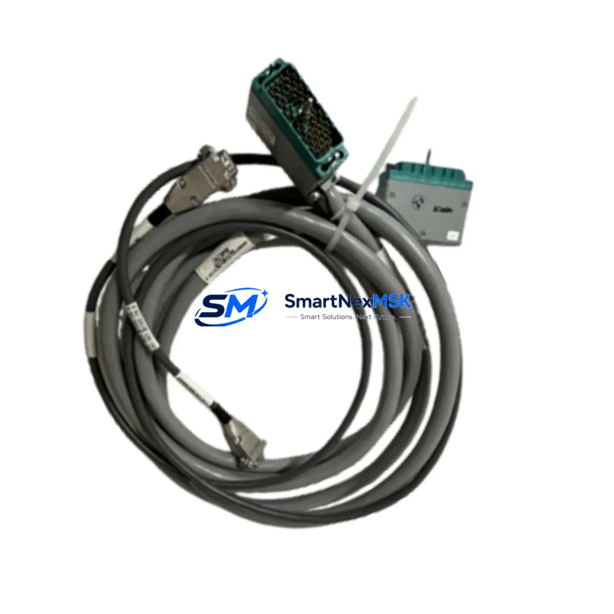
If the I/A Series system includes redundant FBM pairs, the partner module and its switchover logic should be tested during the planned maintenance window. Redundancy relay modules and the associated FBM redundancy cables are often overlooked during single-module replacements and can become single points of failure if not periodically verified.
Procurement engineers building a spare parts strategy around the FBM215-P0922VU should also consider stocking the FBM carrier (ZCP270 or equivalent), CP60 or CP270 control processor modules, and communication interface modules (CIM) relevant to their I/A Series configuration. For sites running older I/A Series versions, sourcing FBM201, FBM202, FBM204, or FBM232 modules as complementary spares ensures broader coverage across the I/O subsystem without requiring a full system upgrade.
Site Replacement Workflow
Step 1 — Pre-replacement verification: Confirm the FBM215-P0922VU part number against the system configuration database and the physical label on the installed module. Cross-reference with the I/A Series hardware configuration tool (Foxboro Control Software / FoxCAE) to confirm slot assignment and I/O channel mapping.
Step 2 — Safe isolation: Place the affected FBM in bypass or manual mode at the DCS operator station. For redundant FBM pairs, initiate a controlled switchover to the partner module before removing the faulty unit. Confirm field loops are in a safe state before proceeding.
Step 3 — Module extraction and inspection: Remove the FBM215-P0922VU from the carrier. Inspect the carrier connector pins and the module’s edge connector for contamination or mechanical damage. Clean with appropriate contact cleaner if required.
Step 4 — Replacement insertion: Insert the new FBM215-P0922VU into the same carrier slot. The module is keyed to prevent incorrect installation. Confirm the module status LED sequence matches the expected initialization pattern per the I/A Series FBM hardware manual.
Step 5 — System restoration and verification: Return the FBM to automatic mode at the DCS. Verify all I/O channels are reading correctly against field instrument values. Confirm HART communication (if applicable) and check the DCS alarm summary for any residual faults. Document the replacement in the site maintenance log.
This workflow supports rapid, low-risk replacement of the FBM215-P0922VU with minimal disruption to the process, preserving system compatibility and maintaining the integrity of the I/A Series control architecture.
Spare Parts Support FAQ
Q1: Is the FBM215-P0922VU compatible with all I/A Series DCS configurations?
The FBM215-P0922VU is designed for the FOXBORO I/A Series DCS platform and is compatible with standard FBM carriers and baseplates used across I/A Series generations. Compatibility with specific control processor versions (CP60, CP270, CP40B, etc.) should be confirmed against your system’s hardware revision and software release level. Our technical team can assist with compatibility verification prior to shipment.
Q2: What testing is performed before the module is shipped?
Every FBM215-P0922VU unit undergoes functional verification prior to dispatch, including power-on self-test confirmation, I/O channel integrity checks, and communication interface validation where applicable. A test report is available upon request. All units are shipped with a 12-month warranty covering manufacturing defects and functional failures under normal operating conditions.
Q3: How should the FBM215-P0922VU be stored as a long-term spare?
Store the module in its original anti-static packaging in a clean, dry environment at 15–30°C with relative humidity below 70% non-condensing. Avoid storage near strong electromagnetic fields or corrosive atmospheres. For long-term inventory (12+ months), inspect the module annually and confirm the edge connector condition before deployment. Shelf life under proper storage conditions exceeds 5 years.
Q4: Can you supply multiple units for a site-wide spare parts program?
Yes. We support bulk procurement for site spare parts programs, planned turnaround projects, and multi-site maintenance contracts. Long-term supply agreements with reserved stock allocation are available for critical modules such as the FBM215-P0922VU. Contact our team to discuss volume pricing, lead time commitments, and consignment stock options.
© 2026 SMARTNEXMSK. All rights reserved.
Original Source: https://smartnexmsk.com
Contact: sales@smartnexmsk.com | +86 18259474341