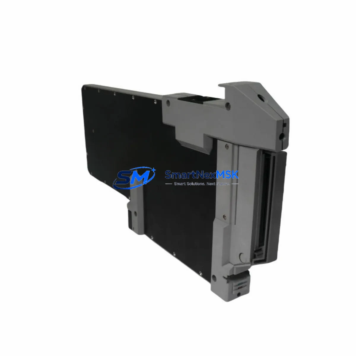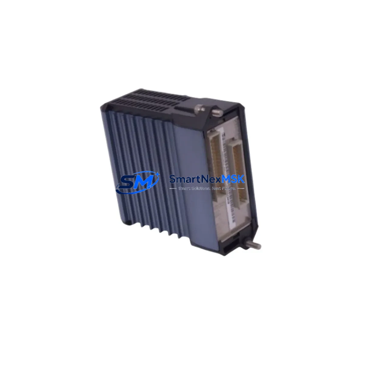
Foxboro FBM242 P0916TA Retrofit-Ready DCS Output Module for I/A Series Control Systems
The Foxboro FBM242 P0916TA is a field-proven analog output module designed for the Foxboro I/A Series Distributed Control System (DCS). As legacy I/A Series installations approach end-of-life or require capacity expansion, the FBM242 P0916TA remains one of the most sought-after retrofit components for engineers managing brownfield upgrades, discontinued spare parts replacement, and control cabinet modernization projects. Whether you are replacing a failed module in a running plant or executing a planned migration from an older Foxboro SPEC 200 or Foxboro 760 series platform, this module provides the output signal integrity and backplane compatibility required for a smooth, low-risk transition.
Sourced from verified industrial supply channels and subject to full functional testing prior to shipment, every FBM242 P0916TA unit shipped by SMARTNEXMSK carries a 12-month warranty covering hardware defects and operational failures under normal service conditions. Our inventory is maintained to support urgent plant shutdowns, scheduled turnarounds, and long-lead procurement programs alike.
Upgrade Compatibility Table
| Parameter | FBM242 P0916TA Specification | Retrofit / Replacement Notes |
|---|---|---|
| Module Type | Analog Output, DCS Field Bus Module | Direct replacement for same-slot I/A Series FBM positions |
| Compatible Platform | Foxboro I/A Series DCS | Verify backplane revision before installation; P0916TA suffix confirms hardware revision |
| Communication Protocol | Nodebus / Fieldbus (I/A Series native) | No protocol converter required for same-generation I/A Series racks |
| Installation Interface | I/A Series FBM backplane slot | Confirm rack model (P0400 series baseplate) and slot addressing before swap |
| Terminal Wiring | Field termination via FBM terminal assembly | Retain existing field wiring; verify terminal block model compatibility (e.g., P0916YA termination assembly) |
| Module Address | Configured via I/A Series system software (IA Series Configurator / FoxCAE) | Re-use existing module address from replaced unit; no re-addressing required for 1-for-1 swap |
| Program Compatibility | Compatible with existing I/A Series control database blocks | No control strategy rewrite required for direct replacement; verify compound and block assignments |
| HMI Integration | Transparent to SCADA / DCS HMI layer | No HMI screen changes required for 1-for-1 module swap |
| Power Consumption | Supplied via I/A Series rack power bus | Verify rack power supply (e.g., P0922VW or equivalent) capacity before adding modules during expansion |
| Warranty | 12 Months | Covers hardware defects under normal operating conditions from shipment date |
Retrofit Planning for Existing Automation Systems
Successful integration of the FBM242 P0916TA into an existing I/A Series installation begins well before the module arrives on site. Engineers should start by auditing the target rack assembly — typically a P0400 series FBM baseplate — to confirm available slot positions, current power budget, and backplane revision compatibility. In multi-rack configurations, the P0922VW rack power supply or its equivalent must be verified to have sufficient headroom to support the additional output module load, particularly in high-density I/O cabinets where multiple FBM modules share a common power rail.
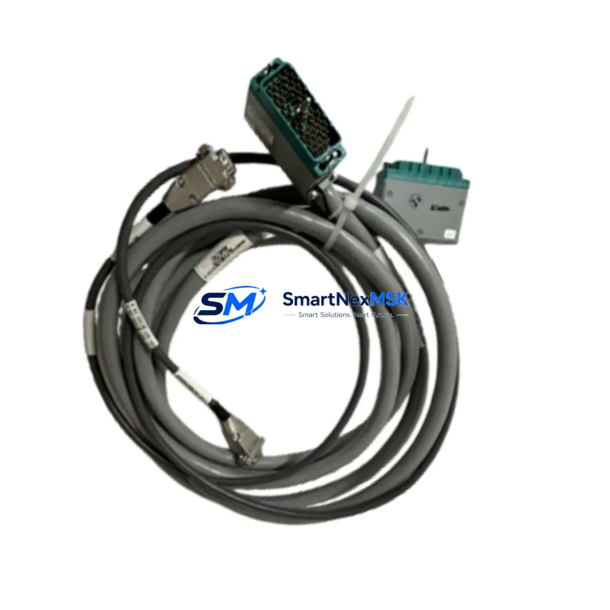
Terminal wiring is one of the most common sources of delay during retrofit projects. The FBM242 uses a dedicated FBM termination assembly — confirm whether the existing P0916YA termination panel is in place and undamaged before scheduling the module swap. In cases where the termination assembly has been modified or replaced with a third-party equivalent, a full point-to-point continuity check against the original loop drawings is strongly recommended before energizing the new module.
For plants migrating from older Foxboro platforms such as the Foxboro SPEC 200 analog control system or the Foxboro 760 series single-loop controllers, the FBM242 P0916TA represents a significant architectural step forward. These legacy systems relied on pneumatic or 4–20 mA hardwired signal paths without digital fieldbus integration. Migrating to the I/A Series architecture requires installing a compatible FBM baseplate and Nodebus communication cable, configuring the new module address within FoxCAE or the I/A Series Configurator, and rebuilding the control strategy using standard I/A Series function blocks. During this process, engineers frequently also commission companion modules such as the FBM201 analog input module for process variable feedback, the FBM207 discrete input module for digital status signals, and the FBM217 discrete output module for valve and actuator control — all of which share the same backplane and communication infrastructure as the FBM242.
Communication link integrity is critical during any I/A Series retrofit. The Nodebus segment connecting the FBM242 to the I/A Series Application Control Environment (ACE) or Control Processor (CP) must be verified for correct termination resistance and cable shielding continuity. In larger DCS architectures, the FBM233 Profibus DP communication module or FBM220 HART multiplexer module may also be present in the same cabinet, and their Nodebus segment assignments must be confirmed to avoid address conflicts after the FBM242 is installed.
I/O expansion projects that add the FBM242 P0916TA to an existing rack should also account for the FBM baseplate termination jumper configuration, which determines whether the new slot is treated as an expansion position or a primary control output. Failure to set this correctly is a common commissioning error that results in the module appearing online in the configurator but failing to drive field outputs. A pre-commissioning checklist covering slot jumper settings, module address assignment, compound download, and loop calibration verification will significantly reduce the risk of extended downtime.
Downtime Control During System Migration
Minimizing unplanned downtime is the primary operational concern when replacing or upgrading DCS output modules in a live production environment. For a 1-for-1 FBM242 P0916TA replacement, the recommended approach is a hot-standby swap procedure: download the existing module configuration from the I/A Series database before removal, confirm the replacement unit’s hardware revision matches the original, and execute the physical swap during a planned control hold or low-demand production window. The I/A Series DCS supports module replacement without full system restart in most configurations, allowing the control strategy to resume output within seconds of the new module coming online.
For more complex migrations — such as moving from a SPEC 200 panel to an I/A Series rack — a phased cutover strategy is strongly recommended. This involves running the new I/A Series output in parallel with the legacy signal path, verifying field device response under the new control loop, and only cutting over the final hardwired connection once the new loop has been validated in manual mode. This approach preserves the original control logic as a fallback and allows operators to maintain process continuity throughout the migration window. Keeping a spare FBM242 P0916TA unit on-site during the cutover period provides an additional safety net against unexpected hardware failures during commissioning.
All FBM242 P0916TA units shipped by SMARTNEXMSK undergo functional output testing prior to dispatch, reducing the risk of DOA (dead-on-arrival) failures that can extend downtime unexpectedly. Units are shipped with original or equivalent protective packaging to prevent transit damage to the backplane connector pins — a common cause of intermittent output faults that are difficult to diagnose after installation.
Retrofit Support FAQ
Q1: Is the FBM242 P0916TA a direct drop-in replacement for other FBM242 suffix variants?
The P0916TA suffix designates a specific hardware revision of the FBM242 module. In most I/A Series installations, P0916TA units are interchangeable with other P0916-series suffix variants (e.g., P0916TB) provided the backplane slot and termination assembly are compatible. Always cross-reference the original module’s part number against the replacement unit’s datasheet and confirm with your I/A Series system documentation before installation.
Q2: Do I need to reconfigure the control database after replacing the FBM242 P0916TA?
For a 1-for-1 hardware replacement in the same rack slot, no database reconfiguration is required. The I/A Series control strategy references the module by its slot address and compound assignment, not by serial number. Simply confirm the module address matches the original, download the compound to the new module, and verify output calibration. If the module is being installed in a new slot or a different rack, a full address assignment and compound download will be required.
Q3: What wiring checks should be performed before powering up the replacement module?
Before energizing the FBM242 P0916TA, verify: (1) field wiring continuity from the termination assembly to the field device, (2) correct polarity on all 4–20 mA output loops, (3) termination assembly model compatibility with the FBM242 backplane connector, and (4) rack power supply voltage within specification. A loop calibrator connected to the output terminals can be used to verify signal integrity before handing control back to the DCS.
Q4: What does the 12-month warranty cover, and how is a warranty claim initiated?
The 12-month warranty covers hardware defects and functional failures under normal operating conditions from the date of shipment. It does not cover damage resulting from incorrect installation, overvoltage, or physical mishandling. To initiate a warranty claim, contact SMARTNEXMSK at sales@smartnexmsk.com or +86 18259474341 with your order reference and a description of the fault. Replacement or repair will be arranged based on fault diagnosis.
© 2026 SMARTNEXMSK. All rights reserved.
Original Source: https://smartnexmsk.com
Contact: sales@smartnexmsk.com | +86 18259474341