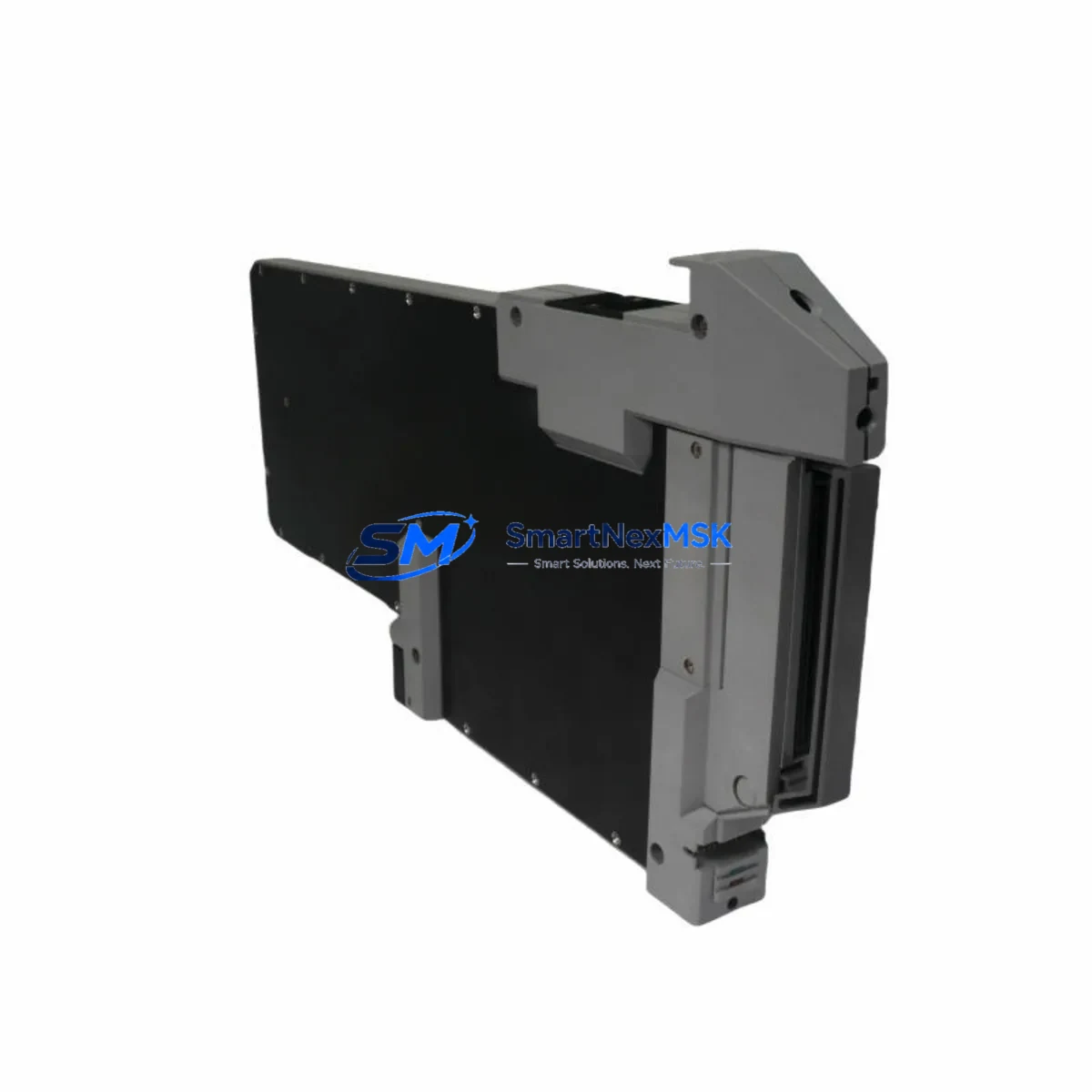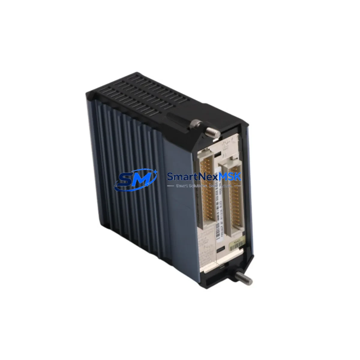
Foxboro FCM10EF Maintenance-Ready Spare for I/A Series Automation
The Foxboro FCM10EF is a Foundation Fieldbus Communication Module (H1) engineered for the Foxboro I/A Series Distributed Control System (DCS). In process-critical industries — including oil & gas, petrochemical refining, power generation, and specialty chemicals — the FCM10EF serves as the essential interface between the I/A Series controller infrastructure and field instrumentation operating on the H1 Foundation Fieldbus segment. An unplanned failure of this module can immediately disrupt loop control, trigger process shutdowns, and result in costly unplanned downtime. Maintaining a verified, tested spare on the shelf is the single most effective strategy for rapid restoration of control.
At SMARTNEXMSK, every FCM10EF unit is sourced from original manufacturing channels, subjected to pre-shipment functional verification, and backed by a 12-month warranty. Our inventory is maintained specifically to support maintenance engineers and procurement teams who cannot afford lead times measured in weeks when a critical DCS node goes offline. We ship globally with full documentation and test records available on request.
Spare Maintenance Table
| Parameter | Specification / Value |
|---|---|
| Model / SKU | FCM10EF |
| Brand | Foxboro (Schneider Electric) |
| Series | I/A Series DCS |
| Module Type | Foundation Fieldbus Communication Module (H1) |
| Fieldbus Standard | IEC 61158 / Foundation Fieldbus H1 |
| H1 Segments Supported | Up to 2 H1 segments per module |
| Communication Protocol | Foundation Fieldbus H1 (31.25 kbit/s) |
| Host Interface | I/A Series Nodebus / FBM Backplane |
| Power Supply | Via FBM Baseplate / Backplane (24 VDC bus) |
| Operating Temperature | 0°C to 60°C (32°F to 140°F) |
| Relative Humidity | 5% to 95% non-condensing |
| Mounting | FBM Baseplate (I/A Series standard) |
| Compatibility | I/A Series FBM Baseplates; Foxboro AW70 / 51B / 51 workstations running IA v8.x and later |
| Origin | United States |
| Certifications | CE, UL (original factory certifications retained) |
| Condition | Original New Surplus / Tested Refurbished (as labeled) |
| Pre-Shipment Test | Functional power-on and communication verification |
| Warranty | 12 Months from date of shipment |
| Typical Application | Process control loops, field device integration, DCS expansion |
| Maintenance Recommendation | Inspect H1 segment wiring, terminators, and power conditioners at each planned outage |
Maintenance Planning for Continuous Operation
When a maintenance or reliability engineer schedules replacement of the FCM10EF, the scope of inspection must extend well beyond the module itself. The Foundation Fieldbus H1 segment is an interconnected electrical system, and a module failure is frequently symptomatic of upstream or downstream stress on associated components.
Begin with the FBM Baseplate (e.g., FBM201 or FBM202 series) that houses the FCM10EF. Inspect baseplate connectors for corrosion, bent pins, or heat discoloration — a degraded baseplate can cause intermittent communication faults that are misdiagnosed as module failures. Next, verify the H1 Fieldbus Power Conditioner output voltage and ripple; an aging or undersized power conditioner is a leading cause of segment instability and should be replaced proactively when the FCM10EF is swapped.
Check the H1 segment terminators at both ends of the fieldbus cable run. Missing or failed terminators cause signal reflections that degrade communication reliability across all devices on the segment — including Foxboro pressure transmitters, flow meters, and valve positioners. Inspect the fieldbus cable itself for insulation damage, moisture ingress at junction boxes, and correct shielding continuity.
At the controller level, review the status of the associated Foxboro CP60 or CP270 Controller Processor module. If the FCM10EF failure was accompanied by controller alarms or watchdog trips, the controller module should be inspected and its firmware version confirmed against the current I/A Series release. Similarly, check the Nodebus interface connections between the FBM enclosure and the controller cabinet — loose or oxidized Nodebus connectors are a known source of intermittent DCS communication faults.
For sites running mixed I/O architectures, also inspect adjacent FBM analog input modules (such as the FBM204 or FBM207) and any HART multiplexers sharing the same enclosure. Thermal stress from a failed module can affect neighboring cards. If the control cabinet houses 24 VDC power supply modules (e.g., Foxboro PS2 or equivalent redundant power supply units), verify output voltage under load and check for capacitor bulging or cooling fan failure — power supply degradation is a silent contributor to module failures across the entire FBM rack.
Where the site uses signal isolators or intrinsic safety barriers on the H1 segment for hazardous area field devices, inspect these components for correct voltage drop and leakage current. Degraded barriers can cause marginal fieldbus signal levels that only manifest as communication errors under load. Finally, document the Device Description (DD) files and function block configurations for all field devices on the affected H1 segment before performing the swap, ensuring that post-replacement re-commissioning is completed without loss of device configuration or loop tuning parameters.
Site Replacement Workflow
Step 1 — Preparation: Obtain the FCM10EF spare and confirm the hardware revision matches or is backward-compatible with the installed baseplate firmware. Download the current module configuration from the I/A Series system database (AIM* historian or ICC) before removing the failed unit. Verify that a compatible replacement is available in your spare parts store before initiating the maintenance window.
Step 2 — Safe Isolation: Place all affected control loops in manual mode at the DCS operator station. Notify the process area of the planned maintenance window. For hot-swap capable baseplates, confirm whether the site’s I/A Series software version supports online module replacement without a full segment shutdown — this can reduce downtime from hours to minutes.
Step 3 — Physical Replacement: Remove the failed FCM10EF by releasing the module locking lever and sliding it clear of the baseplate. Insert the replacement unit firmly until the connector seats fully and the locking lever engages. Verify the module status LED sequence on power-up — a solid green indicates successful initialization and segment communication.
Step 4 — Configuration Restore: Using the I/A Series Integrated Control Configurator (ICC) or equivalent tool, download the saved module configuration to the replacement FCM10EF. Verify all H1 device addresses are recognized and that function block execution is restored without errors or diagnostic alarms.
Step 5 — Loop Verification: Return control loops to automatic mode one at a time, monitoring process variable (PV) and output (OP) values for stability. Confirm that all fieldbus devices on the segment are communicating and that no diagnostic alarms remain active in the DCS alarm management system.
Step 6 — Documentation and Reorder: Record the replacement date, module serial number, and post-replacement test results in the site CMMS (e.g., SAP PM or Maximo). Update the spare parts inventory to trigger reorder of a replacement FCM10EF unit, maintaining minimum stock levels for this critical module. SMARTNEXMSK supports long-term supply agreements to ensure your spare parts store is never depleted for lifecycle-critical components.
Spare Parts Support FAQ
Q1: Is the FCM10EF available as a new original spare, or only as refurbished?
SMARTNEXMSK maintains stock of both original new-surplus and professionally tested refurbished FCM10EF units. Each unit is clearly labeled with its condition grade. All units — regardless of condition — are functionally verified before shipment and covered by our 12-month warranty. For critical applications, specify your preferred condition grade at the time of inquiry.
Q2: How do I confirm compatibility between the FCM10EF and my existing I/A Series baseplate and software version?
Compatibility depends on the FBM baseplate model, the I/A Series software release (v7.x, v8.x, or later), and the fieldbus segment configuration. Provide your baseplate part number and I/A Series software version when placing your order, and our technical team will confirm compatibility before shipment. We cross-reference against Foxboro Field Change Notices (FCNs) to identify any hardware revision requirements.
Q3: What is included in the pre-shipment testing process?
Every FCM10EF undergoes a power-on functional test to verify module initialization, LED status sequence, and communication interface integrity. Units are inspected for physical damage, connector condition, and correct firmware labeling. A test report is available upon request for quality-critical procurement processes.
Q4: What is your policy for long-term spare parts supply and lifecycle support?
SMARTNEXMSK specializes in lifecycle support for legacy and discontinued DCS and PLC hardware. We maintain ongoing inventory of FCM10EF and related I/A Series components to support sites operating beyond the original manufacturer’s active support window. For sites with multiple units or long-term maintenance contracts, we offer reserved stock agreements to guarantee availability. Contact our team to discuss a tailored spare parts support plan for your facility.
© 2026 SMARTNEXMSK. All rights reserved.
Original Source: https://smartnexmsk.com
Contact: sales@smartnexmsk.com | +86 18259474341