FOXBORO P0916CCOC Retrofit-Ready DCS Output Interface Module for I/A Series Control Systems
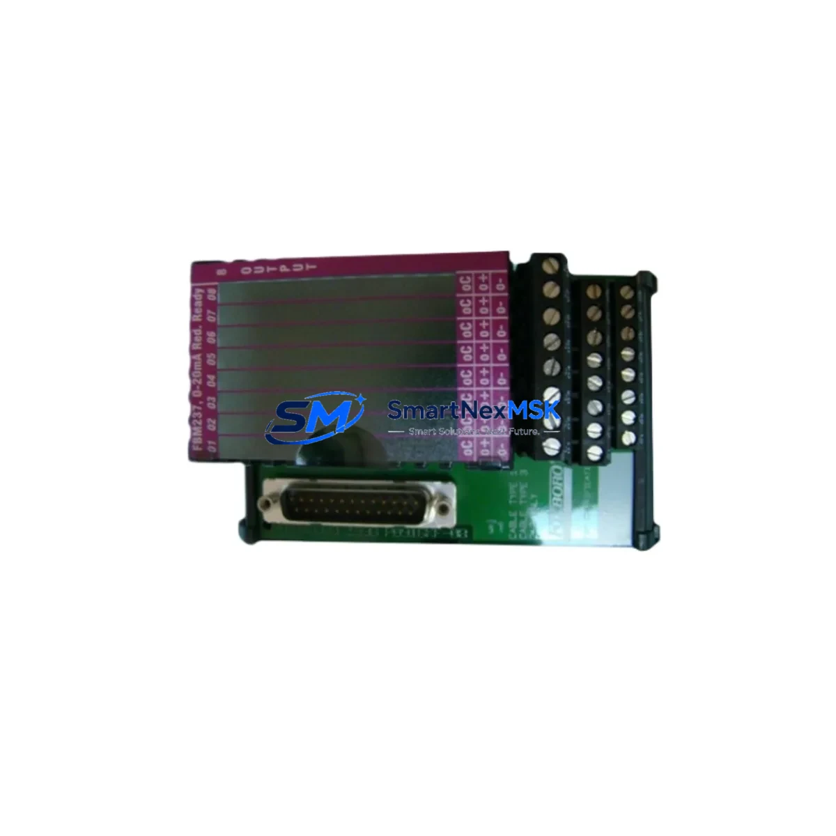
The FOXBORO P0916CCOC is a DCS output interface module engineered for the Foxboro I/A Series distributed control system platform. As legacy I/A Series installations approach end-of-life or require capacity expansion, the P0916CCOC serves as a direct retrofit solution — enabling engineers to restore output functionality, extend system life, and avoid costly full-system migrations. Whether you are replacing a failed module in a running plant or upgrading a control cabinet during a scheduled turnaround, the P0916CCOC delivers verified compatibility with existing I/A Series backplanes, fieldbus wiring, and control processor configurations.
This module is sourced from authorized supply channels, fully tested prior to shipment, and backed by a 12-month warranty. Stock is maintained to support urgent replacement orders with fast global dispatch.
Upgrade Compatibility Table
| Parameter | Details |
|---|---|
| Compatible Platform | Foxboro I/A Series DCS |
| Module Function | DCS Output Interface |
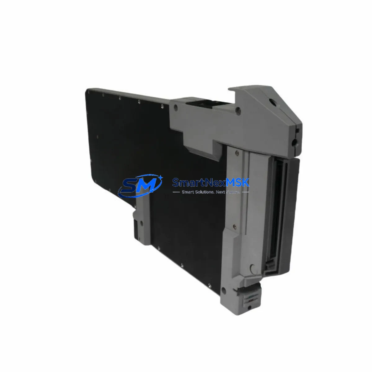
| Backplane Interface | I/A Series standard module bay (compatible with FBM backplane) |
| Installation Type | Direct slot-in replacement; no mechanical modification required |
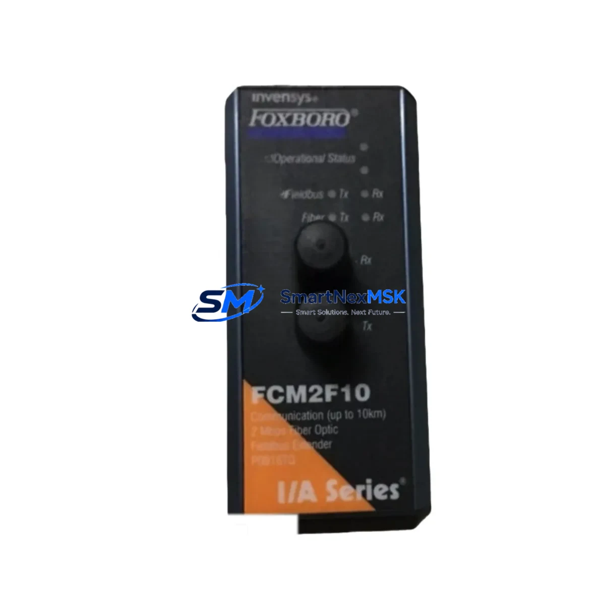
| Communication Compatibility | Nodebus / Fieldbus per I/A Series architecture |
| Replacement Recommendation | Drop-in replacement for failed or end-of-life P0916CCOC units |
| Commissioning Notes | Verify module address assignment in Foxboro AIM historian and control configurator; confirm FBM channel mapping before hot-swap |
| Warranty | 12 months from date of shipment |
Retrofit Planning for Existing Automation Systems
Successful integration of the P0916CCOC into an existing I/A Series installation requires systematic pre-replacement planning. Before removing the failed module, engineers should document the current module address configured in the Foxboro Integrated Control Configurator (ICC) and verify that the replacement unit carries the same hardware revision to ensure firmware compatibility. The I/A Series fieldbus module bay — typically housed in a standard 19-inch control cabinet rack — must be de-energized at the local power distribution panel before physical removal, unless a hot-standby redundancy configuration is in place.
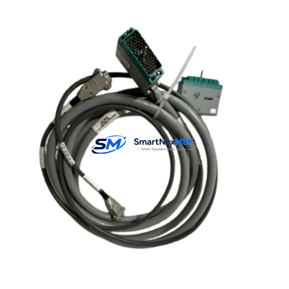
Terminal wiring connected to the output field termination assembly (FTA) should be photographed and labeled prior to disconnection. The FTA itself — often a dedicated Foxboro FBM termination board mounted adjacent to the module bay — remains in place during module swap, which significantly reduces rewiring time and minimizes the risk of field wiring errors. Engineers should confirm that the cable harness connecting the P0916CCOC to the FTA is undamaged and that connector pins are free of corrosion or mechanical stress.
For sites running Foxboro IACC or FoxView HMI software, the replacement module will typically be recognized automatically once the module address is confirmed and the control processor — such as a CP60, CP270, or CP40B — completes its module scan cycle. If the HMI displays a module fault alarm after reinsertion, a forced re-initialization through the Foxboro System Manager console is recommended before resuming process control. Sites using third-party SCADA systems connected via OPC-DA or Modbus TCP should verify that the output tag mapping remains intact after the module replacement.
In multi-rack I/A Series installations, the P0916CCOC may coexist in the same baseplate with analog input modules such as the FBM201 or FBM207, digital output modules, and communication interface modules handling HART or FOUNDATION Fieldbus signals. Confirming that the power supply module — for example a Foxboro P0922VW or equivalent — can sustain the additional load after module replacement is a critical pre-commissioning step. Power budget calculations should account for all active modules in the affected rack segment.
For plants executing a broader I/A Series modernization program — migrating toward the Foxboro Evo platform or integrating with a DeltaV or third-party DCS — the P0916CCOC can serve as a bridge component, maintaining output continuity on legacy loops while new control infrastructure is commissioned in parallel. This phased approach allows production to continue uninterrupted while the new system is validated loop by loop. Programming cables and configuration laptops running Foxboro Control Software Tools (CST) should be on-site during any module commissioning activity to allow real-time parameter verification and alarm acknowledgment.
Downtime Control During System Migration
Minimizing unplanned downtime during a P0916CCOC replacement is achievable through disciplined pre-work and a structured hot-swap or cold-swap protocol. For non-redundant output loops, the recommended approach is to place the affected control loop in manual mode at the DCS operator station before initiating the physical swap. This preserves the last output value at the field device — typically a control valve or variable-speed drive — and prevents process upsets caused by a loss of output signal during the module changeover window.
Once the replacement P0916CCOC is seated and the backplane connection is confirmed, the control processor will perform an automatic module health check. Engineers should monitor the Foxboro System Manager for module status confirmation before returning the loop to automatic control. The entire swap sequence — from loop isolation to auto-mode restoration — can typically be completed within 15 to 30 minutes for a single module, provided all pre-work documentation is complete and the replacement unit has been pre-tested.
For sites where output continuity is critical and no redundancy exists, a temporary hardwired bypass at the FTA terminal strip can maintain field device control during the module swap interval. This technique is particularly effective in applications such as boiler feedwater control, compressor anti-surge, or reactor temperature regulation, where even brief output interruptions carry significant process risk. All bypass activities must be authorized under the site’s management of change (MOC) procedure and documented in the maintenance work order.
Pre-shipment testing performed on every P0916CCOC unit ensures that the replacement module is fully functional on arrival, eliminating the risk of receiving a defective unit during a time-critical maintenance window. Units are tested for output channel integrity, backplane communication, and power consumption compliance before dispatch.
Retrofit Support FAQ
Q1: Is the P0916CCOC a direct drop-in replacement for the original Foxboro module of the same part number?
Yes. The P0916CCOC is a direct replacement for the original Foxboro I/A Series output interface module of the same SKU. It is designed to seat into the existing I/A Series module bay without mechanical modification. Hardware revision compatibility should be confirmed against the installed base revision level before ordering if your site has strict revision-control policies.
Q2: What commissioning steps are required after installing the replacement module?
After physical installation, confirm the module address in the Foxboro Integrated Control Configurator, verify FBM channel-to-tag mapping, and check that the control processor has completed its module scan and reported a healthy status in System Manager. If using FoxView or a third-party HMI, confirm that output tags are updating correctly before returning loops to automatic control. A loop function test — driving the output to a known value and verifying field device response — is recommended as a final commissioning step.
Q3: Can the P0916CCOC be used in a mixed-module rack alongside other I/A Series FBM types?
Yes. The I/A Series architecture supports mixed-module configurations within the same baseplate. The P0916CCOC can coexist with analog input modules, digital I/O modules, and communication interface modules in the same rack. Ensure that the rack power supply has sufficient capacity to support all installed modules, including the replacement unit.
Q4: What does the 12-month warranty cover?
The 12-month warranty covers manufacturing defects and functional failures under normal operating conditions from the date of shipment. Each unit undergoes pre-shipment functional testing. In the event of a warranty claim, SMARTNEXMSK will arrange for a replacement unit to be dispatched promptly to minimize impact on your operations. Warranty claims must be submitted with the original order reference and a description of the observed fault.
© 2026 SMARTNEXMSK. All rights reserved.
Original Source: https://smartnexmsk.com
Contact: sales@smartnexmsk.com | +86 18259474341