FUJI ELECTRIC Z-312J Retrofit-Ready CPU for Z-Series Control Systems
The FUJI ELECTRIC Z-312J is a retrofit-ready CPU module engineered for seamless integration into legacy Z-Series programmable logic controller platforms. As production lines age and original equipment manufacturers discontinue support for older control architectures, the Z-312J provides a verified, drop-in upgrade path that preserves existing wiring infrastructure, backplane slot assignments, and ladder logic programs — minimizing engineering rework and unplanned downtime during system modernization.
Industrial facilities operating FUJI ELECTRIC Z-Series control cabinets frequently encounter challenges when sourcing discontinued spare parts. The Z-312J addresses this directly: it is stocked, tested, and shipped with a 12-month warranty, giving maintenance engineers and procurement teams a reliable supply channel for both emergency replacements and planned retrofit projects.
Upgrade Compatibility Table
| Parameter | Detail |
|---|---|
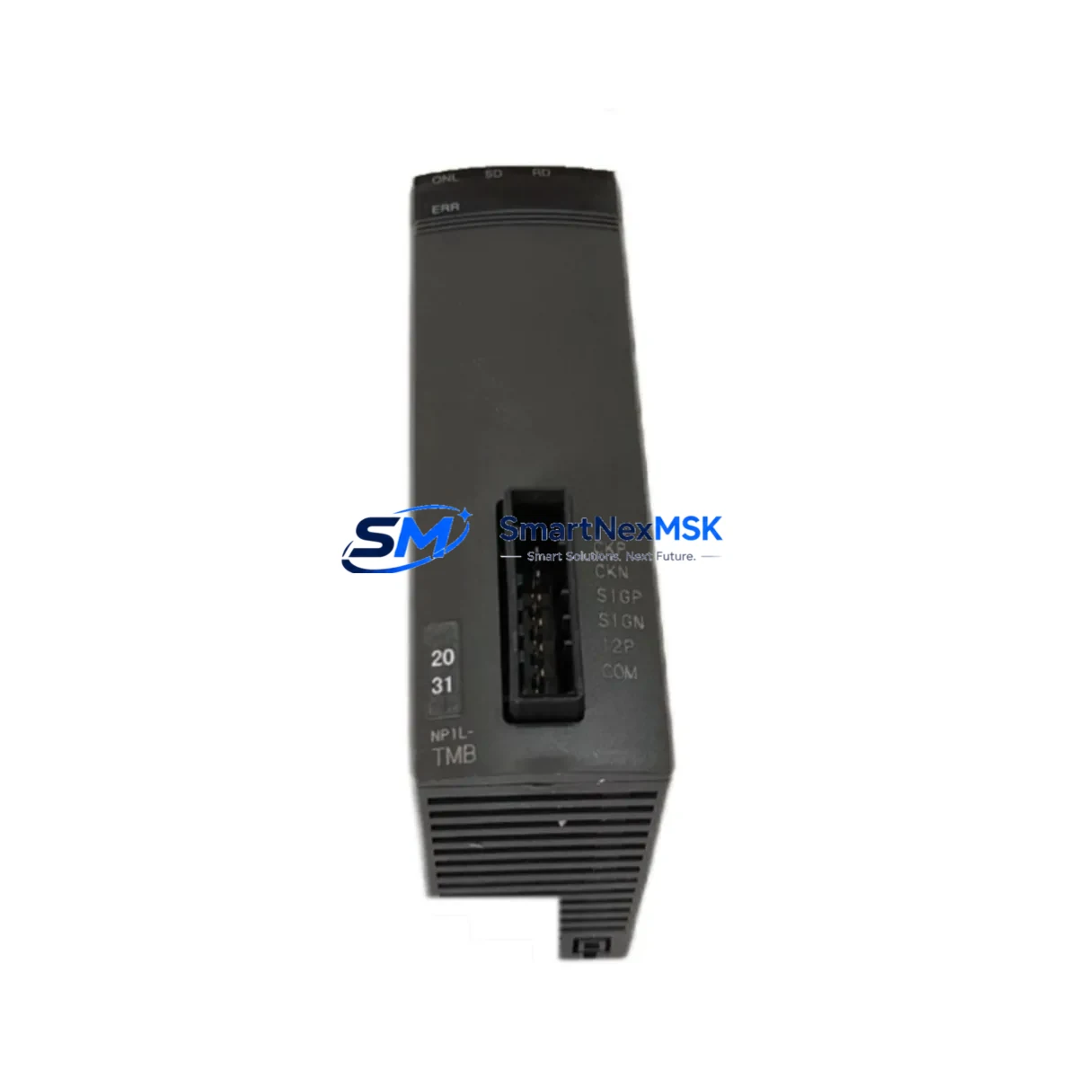
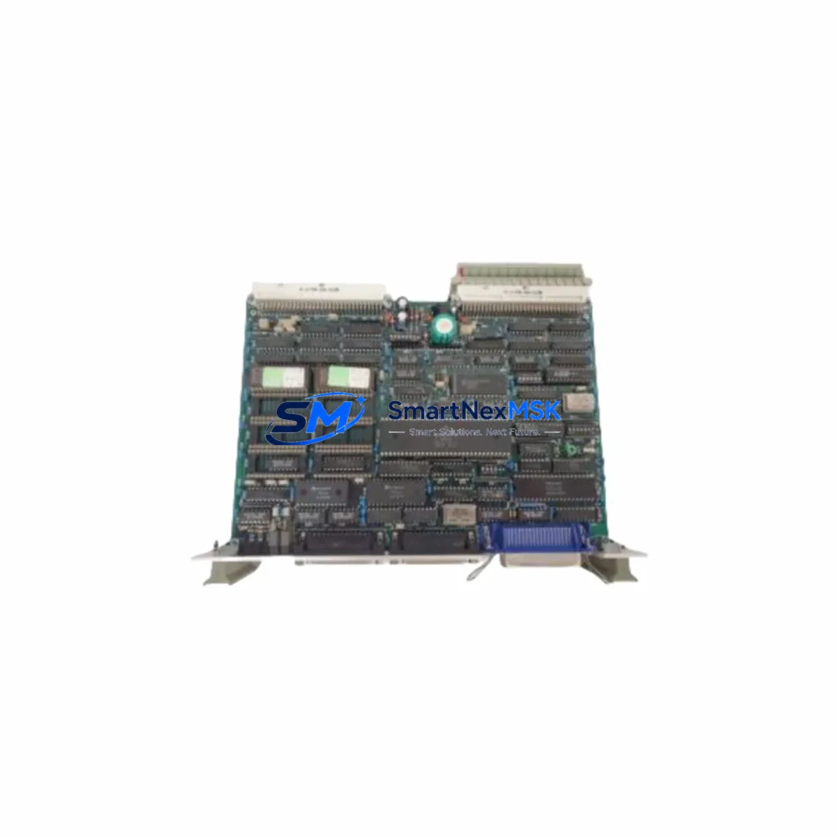
| SKU / Part Number | Z-312J |
| Brand | FUJI ELECTRIC |
| Series | Z-Series PLC |
| Module Type | CPU Module |
| Backplane Interface | Z-Series standard backplane bus (compatible with Z-2 / Z-3 rack chassis) |
| Communication Compatibility | RS-232C programming port; supports FUJI SX-Bus and legacy serial link protocols |
| Power Supply Requirement | 24 VDC via backplane; verify PSU capacity before installation (recommend Z-PW series power supply modules) |
| I/O Expansion | Compatible with Z-Series digital I/O modules (e.g., Z-8EX, Z-16EX input/output expansion units) |
| Programming Interface | FUJI MICREX-F programming software via RS-232C cable (SX-Programmer or equivalent) |
| Replacement Scope | Direct replacement for discontinued Z-312 and Z-312A CPU variants |
| Installation Requirement | Slot 0 of Z-Series rack; confirm DIP switch address settings match original configuration |
| Commissioning Note | Upload and verify ladder program before live restart; confirm HMI tag mapping |
| Warranty | 12 months from date of shipment |
| Origin | Japan |
Retrofit Planning for Existing Automation Systems
A successful Z-312J retrofit begins well before the module arrives on-site. Engineers should start by auditing the existing control cabinet layout: confirm the rack chassis model (typically a Z-2 or Z-3 series backplane), count occupied slots, and document the current power budget drawn by installed I/O modules. The Z-PW24 power supply module is the most common companion unit in Z-Series cabinets; verify its rated output against the combined load of the CPU and all expansion cards before proceeding.
Terminal wiring on Z-Series systems is generally preserved during a CPU swap, since field I/O connections terminate on dedicated input and output modules rather than the CPU itself. However, engineers should photograph and document all terminal block assignments — particularly for analog signal modules such as the Z-4AD analog input module — before powering down. Any custom scaling or offset parameters stored in the original CPU’s data registers must be extracted via the programming cable prior to removal.
Communication links require careful attention during migration. If the existing system uses an SX-Bus communication module for inter-PLC networking or SCADA connectivity, confirm that the Z-312J’s firmware revision supports the same protocol version. For facilities transitioning from legacy RS-232C point-to-point links to Ethernet-based supervision, a FUJI ELECTRIC Z-ETH Ethernet communication module can be added to the rack alongside the Z-312J, enabling Modbus TCP or proprietary SX-Net connectivity without replacing the entire control platform.
HMI panels connected to the Z-Series CPU — commonly FUJI ELECTRIC V-Series or UG-Series operator terminals — communicate via dedicated serial ports. After installing the Z-312J, verify that the HMI’s PLC type selection and station address settings match the new CPU’s configuration. Screen tag addresses and alarm setpoints should be validated against the restored ladder program before returning the line to production.
For I/O expansion, the Z-312J supports the full range of Z-Series expansion units. Common additions during retrofit projects include the Z-16EXD digital output module for relay-driven actuator control and the Z-8AD analog input module for process variable monitoring. When adding new I/O modules to an existing rack, update the I/O assignment table in the CPU configuration and re-verify module addresses to prevent address conflicts with legacy devices.
Programming cables and software are essential retrofit tools. The FUJI SX-Programmer Expert (or the legacy MICREX-F Ladder Editor) connects to the Z-312J via a standard RS-232C programming cable. Before going live, perform a full program upload from the new CPU, compare it against the archived backup, and execute a forced I/O test to confirm all field devices respond correctly.
Downtime Control During System Migration
Minimizing production interruption is the primary concern in any Z-Series CPU replacement. The recommended approach is a cold-swap procedure with pre-staged configuration: before the maintenance window, load the verified ladder program onto the Z-312J in a bench environment, confirm successful compilation, and document all data register values that must be restored after installation.
During the planned shutdown, follow a structured sequence: save the current CPU program and data registers via the programming cable, power down the cabinet using the main isolator, remove the original CPU module from Slot 0, install the Z-312J, restore power, and immediately verify the program checksum via the programming software before enabling outputs. This sequence typically completes within 30–60 minutes for experienced technicians, keeping the maintenance window predictable and contained.
To protect original program logic, always maintain at least two offline backups — one on the engineering workstation and one on removable media — before any hardware change. If the facility uses a SCADA or DCS supervisory layer (such as a FUJI ELECTRIC MICREX-SX DCS node connected upstream), coordinate with the control room to place the affected loop in manual mode during the swap, preventing spurious alarms or automatic responses triggered by the CPU restart sequence.
After the Z-312J is online, run the system in a monitored state for a minimum of one full production cycle before returning to fully automatic operation. Log all I/O states, communication link statuses, and HMI alarm histories during this period to confirm that the retrofit has restored full system functionality. All units supplied by SMARTNEXMSK are pre-tested prior to shipment and covered by a 12-month warranty, reducing the risk of repeat downtime from component failure.
Retrofit Support FAQ
Q1: Is the Z-312J a direct drop-in replacement for the Z-312 and Z-312A?
Yes. The Z-312J is designed as a functional replacement for the discontinued Z-312 and Z-312A CPU modules. It occupies the same Slot 0 position on the Z-Series backplane and is compatible with existing ladder programs written for those variants. Minor DIP switch verification is recommended to confirm station address and memory mode settings match the original configuration.
Q2: What commissioning steps are required after installation?
After physical installation, connect the programming cable to the RS-232C port and use FUJI SX-Programmer or MICREX-F Ladder Editor to upload and verify the ladder program. Perform a forced I/O test on all digital and analog channels, confirm HMI communication link status, and validate data register values before enabling automatic operation. Document all commissioning results for maintenance records.
Q3: Can the Z-312J be used with third-party HMI panels or SCADA systems?
The Z-312J communicates via RS-232C using FUJI’s proprietary SX-Bus protocol. Many third-party HMI panels and SCADA drivers support FUJI ELECTRIC Z-Series protocol via RS-232C or RS-485 adapters. Confirm your HMI or SCADA software’s driver compatibility before installation. For Ethernet-based supervision, adding a Z-ETH communication module to the rack enables Modbus TCP connectivity with most modern SCADA platforms.
Q4: What does the 12-month warranty cover?
All Z-312J units supplied by SMARTNEXMSK are tested for basic functional operation prior to shipment. The 12-month warranty covers manufacturing defects and functional failures under normal operating conditions. It does not cover damage resulting from incorrect installation, overvoltage, or environmental conditions outside the module’s rated specifications. For warranty claims or technical support, contact sales@smartnexmsk.com.
© 2026 SMARTNEXMSK. All rights reserved.
Original Source: https://smartnexmsk.com
Contact: sales@smartnexmsk.com | +86 18259474341