GE CK95BE300 Maintenance-Ready Spare for CR295 Automation
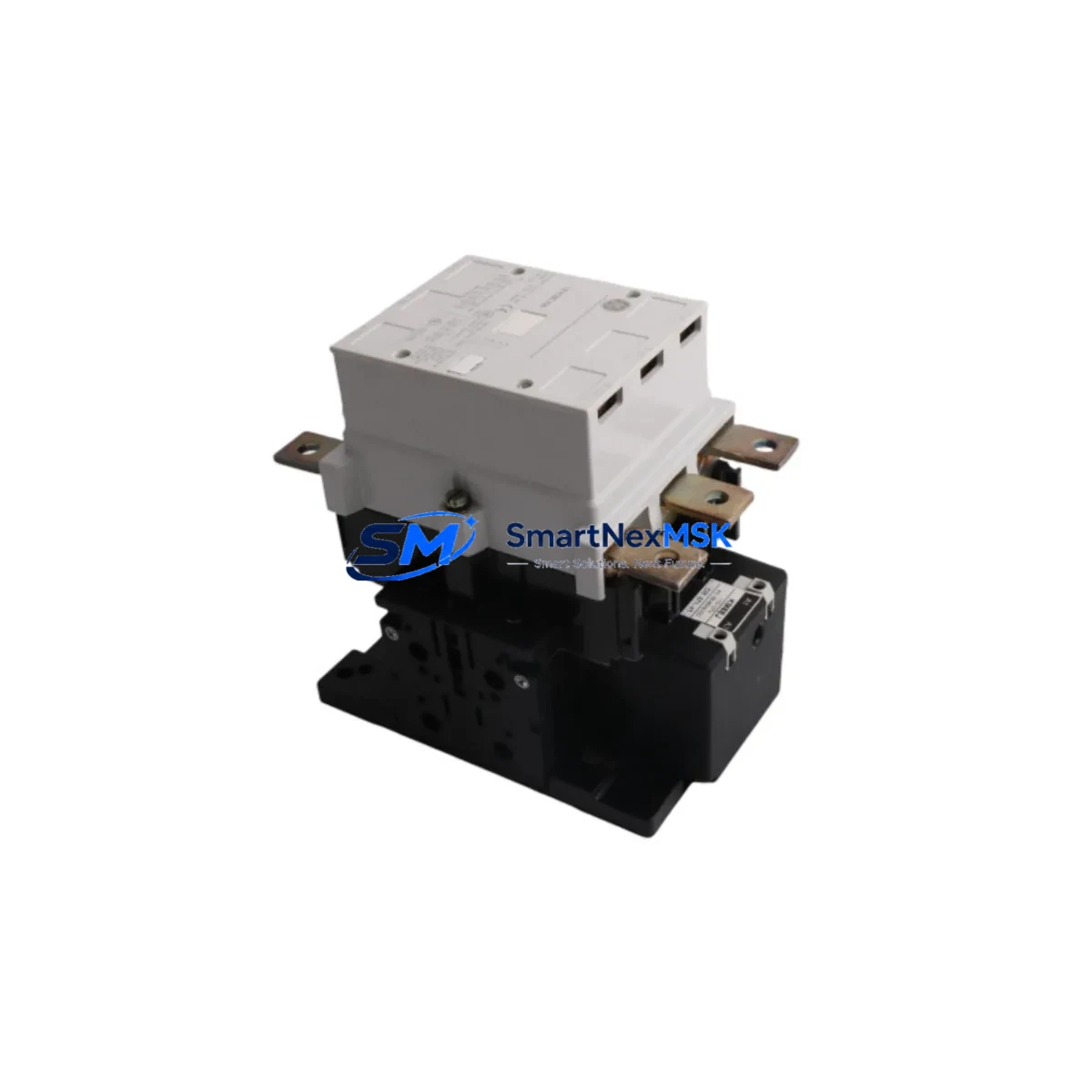
The GE CK95BE300 is an original AC contactor engineered for the CR295 series motor control and industrial automation systems. For maintenance engineers managing aging control panels, motor control centers (MCCs), or distributed automation lines, keeping a verified CK95BE300 spare on the shelf is a direct investment in uptime. Unplanned contactor failure is one of the most common causes of production stoppages in motor-driven processes — from conveyor systems and pump stations to compressor banks and HVAC plant rooms. A pre-tested, shelf-ready CK95BE300 eliminates the sourcing delay that turns a 30-minute swap into a multi-day shutdown.
From a procurement engineering perspective, the CK95BE300 fits directly into CR295-series control architectures without wiring modification, making it a zero-risk drop-in replacement. Its coil voltage, pole configuration, and frame dimensions are factory-matched to the original GE specification, ensuring compatibility with existing overload relays, auxiliary contact blocks, and mounting rails already installed in the cabinet.
SMARTNEXMSK supplies the CK95BE300 as a genuine original component, individually tested before shipment, with a 12-month warranty covering manufacturing defects. Long-term supply continuity is maintained for customers managing legacy GE CR295 installations where OEM support has been reduced or discontinued.
Spare Maintenance Table
| Parameter | Specification |
|---|---|
| Part Number | CK95BE300 |
| Brand | GE (General Electric) |
| Series | CR295 |
| Product Type | AC Contactor |
| Coil Voltage | 120V AC / 240V AC (confirm with nameplate) |
| Pole Configuration | 3-Pole (standard CR295 frame) |
| Rated Current | Per CR295 series rating (confirm with application) |
| Mounting | DIN rail / panel mount, CR295-compatible |
| Auxiliary Contacts | Compatible with GE CR295 auxiliary contact blocks |
| Overload Relay Compatibility | GE CR295 series overload relays |
| Application Environment | Industrial MCC, motor control panels, automation cabinets |
| Origin | USA |
| Warranty | 12 Months (manufacturing defects) |
| Pre-shipment Testing | Yes — coil actuation, contact resistance, insulation verified |
| Condition | Original, new |
Maintenance Planning for Continuous Operation
When a CK95BE300 contactor is flagged during a scheduled inspection or fails in service, experienced maintenance engineers know that the contactor itself is rarely the only component that needs attention. A thorough cabinet inspection at the time of replacement significantly reduces the risk of a repeat callout.
Start with the control power supply feeding the contactor coil circuit. A degraded 24VDC or 120VAC control transformer can cause coil chatter, premature contact wear, and nuisance trips — symptoms that are often misdiagnosed as contactor failure. Verify output voltage under load before energizing the replacement unit.
Inspect the GE CR295 overload relay mounted below the contactor. Overloads in long-running motor circuits accumulate thermal stress; if the contactor failed due to a motor overload event, the overload relay’s bimetal elements may have been stressed beyond their calibration point. A replacement CK95BE300 paired with a fatigued overload relay is a short-term fix at best.
Check all control wiring terminals and DIN rail terminal blocks in the coil circuit. Loose or corroded terminals on the A1/A2 coil connections are a leading cause of intermittent contactor operation and should be re-torqued to specification during every planned replacement.
If the motor circuit includes a GE CR295 auxiliary contact block for interlocking or status feedback to a PLC or DCS, verify contact continuity and mechanical operation. Auxiliary contacts in high-cycle applications wear independently of the main power contacts and are a common source of false status signals in SCADA systems.
For installations where the CK95BE300 is part of a reversing contactor pair, inspect the mechanical and electrical interlock assembly between both contactors. Interlock wear is accelerated in frequent-start applications and is often overlooked during single-contactor replacements.
Review the motor branch circuit fusing or circuit breaker upstream of the contactor. A fault that caused the contactor to fail may have also stressed the fuse elements or tripped a breaker’s thermal memory. Replacing fuses as a precaution during unplanned contactor changes is standard practice in high-availability plants.
Where the motor is controlled via a GE PLC I/O module or a third-party DCS analog output card, confirm that the output channel driving the contactor coil is functioning within specification. A failing digital output with elevated leakage current can hold a contactor coil partially energized, causing contact bounce and accelerated wear on the new unit.
In cabinets that also house signal isolators or relay output modules for motor run/stop commands, verify isolation integrity. Ground loops introduced through degraded isolators can inject noise into the coil circuit, causing erratic contactor behavior that is difficult to trace without proper instrumentation.
Finally, log the replacement in your CMMS (Computerized Maintenance Management System) with the installation date, coil voltage confirmed, and torque values recorded. This data supports future predictive maintenance intervals and helps procurement engineers justify strategic spare holding for the CK95BE300 and associated CR295 series components.
Site Replacement Workflow
Step 1 — Isolation and Lockout/Tagout: De-energize the motor branch circuit at the upstream disconnect or circuit breaker. Apply LOTO per site procedure. Verify absence of voltage at the contactor line-side terminals with a calibrated meter.
Step 2 — Document existing wiring: Photograph or sketch the A1/A2 coil connections, main power terminal assignments (L1/L2/L3 → T1/T2/T3), and any auxiliary contact wiring before removal. The CR295 frame is consistent across the series, but field modifications are common in older installations.
Step 3 — Remove the failed unit: Disconnect coil wiring first, then main power terminals. Release the DIN rail clip or panel mounting screws. Remove any auxiliary contact blocks or mechanical interlock brackets — these transfer directly to the CK95BE300 replacement.
Step 4 — Install CK95BE300: Mount the new contactor, reattach auxiliary blocks and interlock hardware, and reconnect wiring per the documented layout. Torque all terminals to the GE CR295 specification (typically 2.5–4 Nm for main terminals; confirm with the product datasheet).
Step 5 — Functional verification: Before restoring motor load, energize the control circuit only and verify coil pull-in at rated voltage, auxiliary contact state changes, and interlock operation. Then restore main power and confirm motor start/stop under no-load conditions before returning to full production.
Step 6 — Update maintenance records: Record the replacement in the CMMS, note the failed unit’s service hours, and schedule the next inspection interval. For high-cycle applications, consider reducing the planned replacement interval for the next CK95BE300 unit in service.
Spare Parts Support FAQ
Q: Is the CK95BE300 a direct drop-in replacement for older CR295 series contactors?
A: Yes. The CK95BE300 is manufactured to the original GE CR295 frame and electrical specification. It accepts existing auxiliary contact blocks, overload relays, and mechanical interlocks from the CR295 series without modification. Always confirm coil voltage against the existing installation before ordering.
Q: What pre-shipment testing does SMARTNEXMSK perform on the CK95BE300?
A: Each unit undergoes coil actuation testing at rated voltage, main contact resistance measurement, insulation resistance verification, and mechanical operation check before dispatch. Test records are available on request. The 12-month warranty covers manufacturing defects from the date of shipment.
Q: How should the CK95BE300 be stored as a long-term shelf spare?
A: Store in the original packaging in a dry, temperature-controlled environment (5–40°C, <85% RH non-condensing). Avoid storage near high-vibration equipment. Inspect coil and contact condition annually if the unit remains in storage beyond 12 months. SMARTNEXMSK can advise on extended storage protocols for critical spare programs.
Q: Can SMARTNEXMSK support ongoing supply for legacy GE CR295 installations?
A: Yes. SMARTNEXMSK maintains long-term sourcing capability for GE CR295 series components including the CK95BE300, supporting customers with aging automation infrastructure where OEM availability has declined. Contact our team to discuss blanket order arrangements, consignment stock, or multi-site spare programs.
© 2026 SMARTNEXMSK. All rights reserved.
Original Source: https://smartnexmsk.com
Contact: sales@smartnexmsk.com | +86 18259474341


