GE DS200DCFBG1BLC Retrofit-Ready DC Power Supply for Mark V Control Systems
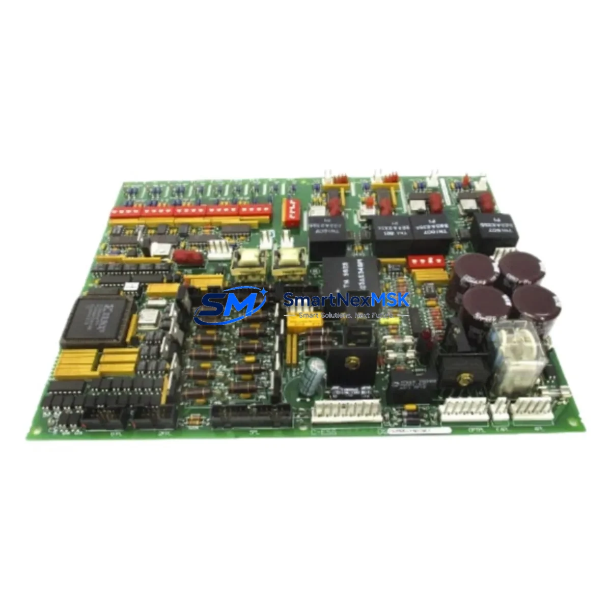
The GE DS200DCFBG1BLC is a DC power supply board engineered for direct retrofit and drop-in replacement within GE Mark V turbine control systems. As legacy Mark V panels approach end-of-support and original spare parts become increasingly scarce, the DS200DCFBG1BLC provides a verified, specification-matched solution for plant engineers and system integrators managing turbine control cabinet upgrades, power distribution modernization, and unplanned outage recovery. Whether you are replacing a failed unit on an emergency basis or executing a planned control system modernization, this board is stocked, tested, and ready for immediate dispatch with a 12-month warranty.
The DS200DCFBG1BLC supplies regulated DC power to the Mark V and processor racks, interfacing directly with the Mark V backplane and terminal board assemblies. Its output rails are compatible with the voltage and current demands of the TCCA, TCDA, TCQA, and TCRA processor cards that form the core of the Mark V triple-redundant control architecture. When retrofitting a failed power supply, engineers must verify the input AC voltage range, confirm the backplane connector pinout against the original wiring diagram, and check that the output DC bus voltage is within the tolerance window required by the downstream I/O modules before energizing the replacement board.
Upgrade Compatibility Table
| Parameter | DS200DCFBG1BLC Specification | Retrofit Notes |
|---|---|---|
| Target Platform | GE Mark V Turbine Control System | Verify panel revision (R, S, T core) before installation |
| Backplane Interface | Mark V standard backplane connector | Confirm connector orientation; no adapter required for standard Mark V racks |
| Input Voltage | 120/240 VAC, 50/60 Hz | Match to site supply; check upstream transformer tap setting |
| Output DC Bus | ±15 VDC, +5 VDC regulated rails | Measure output under load before connecting processor cards |
| Communication Compatibility | Passive power board; no protocol dependency | No firmware or protocol configuration required |
| Replacement Candidates | DS200DCFBG1A, DS200DCFBG1B variants | Cross-reference suffix letter; confirm hardware revision with GE documentation |
| Installation Requirement | ESD precautions, torque spec per GE GEH-6421 | De-energize panel; follow Mark V maintenance manual lockout procedure |
| Commissioning Check | DC bus voltage measurement, load test | Use calibrated multimeter; verify all rails before restoring processor power |
| Warranty | 12 Months | Covers manufacturing defects; excludes damage from incorrect installation |
Retrofit Planning for Existing Automation Systems
A successful Mark V power supply retrofit begins well before the replacement board arrives on site. The first step is a full audit of the existing control cabinet: document the current wiring of the terminal board assemblies, photograph the backplane slot assignments, and record the addresses of all I/O modules installed in the Mark V I/O racks. The DS200DCFBG1BLC powers not only the processor cards but also the analog and digital I/O boards that feed signals to the turbine protection and sequencing logic. Any interruption to the DC supply rails will affect the TCQA triple-modular redundancy voting logic, so the replacement sequence must be planned to minimize the window during which the control system is de-energized.
In a typical Mark V cabinet, the power supply board sits in a dedicated slot within the core rack alongside the TCCA core processor, the TCDA diagnostic card, and the TCRA redundancy management card. Before removing the DS200DCFBG1BLC, engineers should export the current application program from the Mark V using the GE Toolbox software and store a verified backup on an isolated engineering workstation. This protects the turbine sequencing logic, the protection setpoints, and the HMI display tag assignments from any risk of data loss during the hardware swap.
The retrofit also requires attention to the communication links that connect the Mark V to the plant DCS or SCADA layer. In many installations, the Mark V communicates via a Genius Bus or an Ethernet gateway module. The DS200TCCAG1 communication card and associated Genius Bus Interface Module should be inspected for firmware version compatibility whenever the power supply is replaced, as a power cycle can occasionally expose latent communication faults that were masked during normal operation. Similarly, the UCVEH or UCVEH2 HMI workstation should be checked to confirm that all dynamic display points are refreshing correctly after the panel is re-energized.
For sites where the Mark V is integrated with a modern DCS via an OPC gateway, the retrofit window is also an opportunity to verify the OPC server tag list and confirm that the Modbus or SRTP register map has not drifted from the current application program. Replacing the DS200DCFBG1BLC without verifying the communication layer can result in silent data errors that are difficult to diagnose after the turbine returns to service. A structured pre-commissioning checklist covering the power supply output rails, the I/O module status LEDs, the Genius Bus health indicators, and the HMI alarm summary will reduce the risk of extended downtime.
Additional components commonly required during a Mark V power supply retrofit include the DS200TCQAG1B triple-redundancy card, the DS200SDCIG2A DC-to-DC converter board, the DS200IIBDG1A inter-board interface module, the DS200TCDAG1A diagnostic and trip card, and the Mark V programming cable set used to connect the engineering workstation to the TCCA serial port. Having these components staged and tested before the maintenance window opens is the most effective way to control total outage duration.
Downtime Control During System Migration
Minimizing turbine downtime during a Mark V power supply replacement requires a disciplined pre-outage preparation process. The replacement DS200DCFBG1BLC should be bench-tested before the maintenance window: apply the correct input AC voltage, measure all DC output rails under a representative load, and confirm that the board passes the GE factory acceptance criteria before it is transported to the site. A board that fails on the bench can be exchanged before the turbine is taken offline, avoiding a second outage.
During the outage, the recommended sequence is to export and verify the Mark V application program, de-energize the panel following the site lockout/tagout procedure, remove the failed DS200DCFBG1BLC, install the replacement board, torque all backplane connectors to specification, and restore power in stages — first verifying the DC bus rails before reconnecting the processor cards. The TCCA, TCDA, and TCQA cards should be allowed to complete their self-test sequence before the turbine control logic is re-enabled. The entire swap, including pre-checks and post-energization verification, can typically be completed within a two-to-four hour maintenance window when the replacement board has been pre-tested and all tools and documentation are staged in advance.
After the panel is re-energized, the HMI alarm summary should be reviewed for any new first-out alarms that appeared during the power cycle. The Genius Bus communication status, the I/O module ready indicators, and the triple-redundancy voting status on the TCQA card should all be confirmed healthy before the turbine is returned to automatic control. A post-commissioning test run at reduced load, with the control engineer monitoring the key process variables on the HMI, provides the final confirmation that the DS200DCFBG1BLC retrofit has been completed successfully.
Retrofit Support FAQ
Q1: Is the DS200DCFBG1BLC a direct drop-in replacement for earlier DS200DCFBG1A and DS200DCFBG1B variants?
In most Mark V installations, yes. The BLC suffix denotes a later hardware revision with improved component tolerances. The backplane connector, output voltage rails, and physical form factor are identical to earlier variants. However, we recommend cross-referencing the suffix letter against your panel’s wiring diagram and the GE Mark V maintenance manual (GEH-6421) before installation to confirm compatibility with your specific hardware revision.
Q2: What pre-shipment testing is performed on the DS200DCFBG1BLC?
Every DS200DCFBG1BLC unit is powered up and load-tested prior to shipment. DC output rail voltages are measured and recorded, and the board is inspected for component damage, cold solder joints, and capacitor condition. A test report is available upon request. All units are shipped with a 12-month warranty covering manufacturing defects and verified functional performance.
Q3: Do I need to reconfigure any parameters after installing the replacement board?
The DS200DCFBG1BLC is a passive power supply board and does not store application parameters or firmware. No software configuration is required after installation. However, the Mark V application program should be verified in the GE Toolbox after the panel is re-energized to confirm that all I/O module addresses, protection setpoints, and sequencing logic are intact following the power cycle.
Q4: What is the lead time and warranty coverage?
In-stock units are dispatched within 1–2 business days. The DS200DCFBG1BLC carries a 12-month warranty from the date of shipment, covering manufacturing defects and verified functional failures under normal operating conditions. Expedited shipping is available for emergency outage situations. Contact our team for availability confirmation and technical support prior to ordering.
© 2026 SMARTNEXMSK. All rights reserved.
Original Source: https://smartnexmsk.com
Contact: sales@smartnexmsk.com | +86 18259474341


