GE DS200DTBCG1AAA Maintenance-Ready Spare for Mark VI Automation
The GE DS200DTBCG1AAA is an original output termination module engineered for GE Mark VI Speedtronic turbine control systems. In industrial power generation and heavy process environments, unplanned downtime caused by a failed termination board can cascade into extended outages affecting entire turbine trains. Stocking a verified DS200DTBCG1AAA spare is a frontline strategy for maintenance engineers who need to restore control system integrity within a single maintenance window.
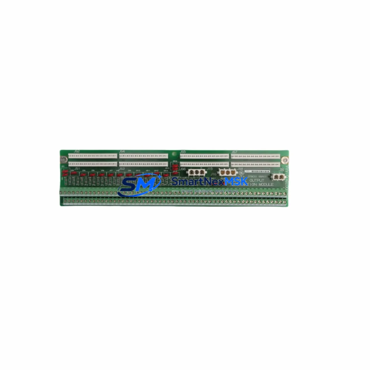
This module serves as the critical interface between the Mark VI controller backplane and field I/O wiring, routing discrete output signals to actuators, solenoids, and relay panels. Its failure mode — often presenting as loss of output channel response, nuisance trips, or intermittent contact closure — is frequently misdiagnosed at the relay or actuator level before the termination board is identified as the root cause. Having a pre-tested DS200DTBCG1AAA on the shelf eliminates diagnostic delay and allows maintenance teams to swap, verify, and return the unit to service with confidence.
Each unit supplied by SMARTNEXMSK is functionally tested prior to dispatch and covered by a 12-month warranty, supporting both emergency replacement and planned overhaul cycles.
Spare Maintenance Table
| Part Number | DS200DTBCG1AAA |
| Brand | GE (General Electric) |
| Series | Mark VI Speedtronic Turbine Control |
| Module Type | Output Termination Board |
| Compatible Controllers | GE Mark VI, Mark VIe (with adapter verification) |
| Output Type | Discrete output termination, relay-driven field circuits |
| Mounting | DIN-rail / backplane slot per Mark VI cabinet standard |
| Operating Temperature | 0°C to 60°C (standard industrial enclosure) |
| Application Environment | Gas turbine, steam turbine, compressor control panels |
| Condition | Original, functionally tested before shipment |
| Compatibility Verification | Cross-reference by full part number and revision suffix |
| Maintenance Recommendation | Inspect wiring harness, connector pins, and adjacent I/O boards during replacement |
| Warranty | 12 Months from date of shipment |
| Lead Time | Ships within 1–3 business days upon order confirmation |
Maintenance Planning for Continuous Operation
When a DS200DTBCG1AAA output termination module is flagged for replacement during a scheduled outage or emergency callout, experienced maintenance engineers treat the event as an opportunity to audit the surrounding control cabinet. The Mark VI architecture distributes I/O across multiple termination boards, and a failure in one output termination zone often indicates thermal stress, connector fatigue, or power supply ripple affecting adjacent components.
During the same maintenance window, technicians should inspect the DS200SDCIG1A power distribution board, which supplies regulated voltage to the termination layer. A degraded power supply can accelerate output board failures and cause intermittent channel faults that are difficult to reproduce under normal diagnostic conditions. Similarly, the DS200TCQAG1BHF I/O terminal board and DS200IOCAG1B I/O controller board share the same backplane environment and should be visually inspected for burn marks, corrosion, or loose seating.
For relay-driven output circuits, the associated DS200RTBAG1A relay termination board should be checked alongside the DS200DTBCG1AAA. Relay contact wear and coil resistance drift are common in high-cycle turbine applications, and replacing the output termination board without verifying relay integrity can result in a repeat fault within weeks. Fuse holders and DS200FTRPG1A fuse termination panels in the same output loop should also be inspected and fuses replaced as a precaution.
Communication integrity between the Mark VI controller and the HMI workstation should be verified after any termination board swap. The DS200TCDAG1A communication board and associated Ethernet or serial links to the GE Cimplicity HMI or third-party SCADA should be tested for stable data exchange. Signal isolation modules in the analog output loops — particularly where 4–20 mA signals interface with positioners or variable speed drives — should be confirmed for correct zero and span calibration.
For sites running aging Mark VI cabinets beyond their original design life, a proactive spare parts list should include the DS200EXPSG1ADA expansion power supply, DS200TCEAG1A Ethernet communication board, and a set of DS200DTBCG1AAA output termination modules as rotating spares. This approach supports a controlled lifecycle extension strategy without requiring a full Mark VIe migration.
Site Replacement Workflow
Step 1 — Isolation and Permit: Obtain a valid work permit and isolate the affected output circuit at the field junction box before opening the Mark VI cabinet. Confirm that the turbine or driven equipment is in a safe, locked-out state.
Step 2 — Document Current Configuration: Photograph the existing DS200DTBCG1AAA wiring harness, connector positions, and any field-applied labels before disconnection. Record the module revision suffix (G1AAA) to confirm the replacement unit is an exact match.
Step 3 — Module Removal: Release the backplane locking tab, disconnect the field wiring connector, and slide the module out of its slot. Inspect the connector pins on both the module and the backplane for bent contacts or oxidation.
Step 4 — Replacement Installation: Seat the new DS200DTBCG1AAA firmly into the backplane slot, reconnect the field wiring harness in the documented sequence, and verify connector latch engagement. Do not force the module — misalignment can damage backplane pins.
Step 5 — Power-Up and Functional Test: Restore cabinet power and observe the Mark VI diagnostic display for fault codes. Cycle each output channel from the HMI or local test panel and confirm field device response. Log the replacement in the site maintenance management system (CMMS).
Step 6 — Return-to-Service: Remove isolation, restore the work permit, and confirm with the control room that all output channels are reading correctly before releasing the unit to normal operation.
This workflow minimizes total downtime to under two hours for a prepared maintenance team with a pre-tested spare on hand, compared to multi-day delays when sourcing a replacement reactively.
Spare Parts Support FAQ
Q1: Is the DS200DTBCG1AAA compatible with both Mark VI and Mark VIe systems?
The DS200DTBCG1AAA is designed for the GE Mark VI Speedtronic platform. Compatibility with Mark VIe requires verification of the backplane connector standard and I/O mapping. Contact our technical team with your cabinet serial number and existing board revision for a confirmed cross-reference before ordering.
Q2: How is each unit tested before shipment?
Every DS200DTBCG1AAA supplied by SMARTNEXMSK undergoes functional testing that verifies output channel continuity, connector integrity, and board-level power response. A test report is available upon request. Units are packed in anti-static packaging with foam protection to prevent transit damage.
Q3: What does the 12-month warranty cover?
The 12-month warranty covers manufacturing defects and functional failures under normal operating conditions from the date of shipment. It does not cover damage caused by incorrect installation, overvoltage events, or physical mishandling. Warranty claims are processed with a return authorization and typically resolved within 5–7 business days.
Q4: Can I order multiple units for a standing spare parts inventory?
Yes. SMARTNEXMSK supports bulk spare parts orders for maintenance departments and EPC contractors managing multiple Mark VI installations. Volume pricing and priority lead times are available for standing purchase orders. Contact our sales team to discuss a tailored spare parts supply agreement aligned with your planned maintenance schedule.
© 2026 SMARTNEXMSK. All rights reserved.
Original Source: https://smartnexmsk.com
Contact: sales@smartnexmsk.com | +86 18259474341


