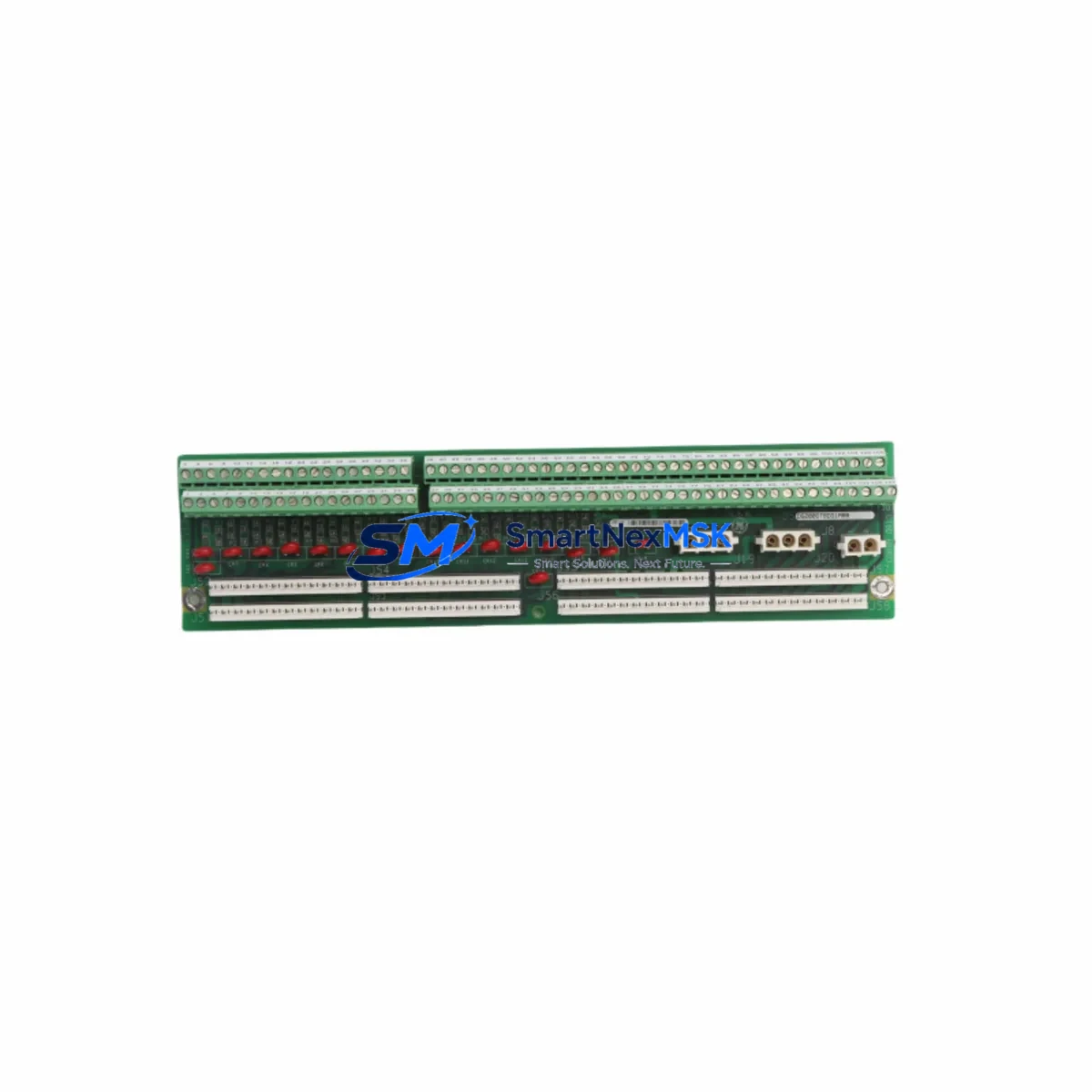
GE DS200DTBDG1ABB Retrofit-Ready Termination Board for Mark VI Control Systems
The GE DS200DTBDG1ABB is a high-reliability DCS termination board engineered for the GE Mark VI distributed control system platform. As legacy Mark V and early Mark VI installations approach end-of-life, the DS200DTBDG1ABB has become a critical component in plant-wide retrofit programs, enabling engineers to modernize I/O wiring infrastructure without replacing the entire control cabinet. Whether you are executing a phased upgrade, recovering from an unplanned failure, or consolidating spare-parts inventory, this board delivers the electrical and mechanical compatibility required for a smooth, low-risk transition.
Sourced from verified industrial supply channels and subject to full functional testing prior to shipment, each DS200DTBDG1ABB unit is backed by a 12-month warranty covering manufacturing defects and operational failures under normal service conditions. Our team maintains ready stock to support urgent maintenance windows and scheduled turnarounds alike.
Upgrade Compatibility Table
| Parameter | DS200DTBDG1ABB Specification | Retrofit Notes |
|---|---|---|
| Platform Compatibility | GE Mark VI DCS | Also compatible with select Mark VI e configurations; verify firmware revision |
| Mounting / Installation | Standard Mark VI backplane rail mount | Direct drop-in; no bracket modification required for same-generation racks |
| Terminal Wiring | Screw-terminal field wiring interface | Retain existing field cable schedule; verify terminal numbering against original I/O drawing |
| Communication Interface | IONet / ARCNET backplane bus | Protocol-transparent replacement; no gateway or converter required |
| Power Supply Requirement | +5 VDC / +24 VDC via backplane | Confirm PSPS power supply module (e.g. DS200PSDAG1A) capacity before hot-swap |
| Module Address | Configured via ToolboxST software | Re-use existing address assignment; no re-addressing required if slot position is unchanged |
| HMI / SCADA Impact | Tag-transparent replacement | Existing Cimplicity or third-party HMI screens require no modification |
| Program Logic Compatibility | Full compatibility with existing ToolboxST application code | No re-download required if firmware version matches; verify with GE release notes |
| Replacement Recommendation | Direct replacement for DS200DTBDG1ABB; evaluate DS200DTBCG1A for upgraded I/O density | Consult GE Mark VI migration guide for cross-series upgrades |
| Warranty | 12 Months | Covers manufacturing defects and functional failures under normal operating conditions |
Retrofit Planning for Existing Automation Systems
A successful DS200DTBDG1ABB retrofit begins well before the maintenance window opens. Engineers should pull the original I/O assignment sheets and cross-reference each field terminal against the replacement board’s wiring diagram. In most Mark VI installations, the termination board sits between the field junction box and the DS200IOCAG1A I/O controller module, so confirming the ribbon-cable connector orientation and locking tab condition is a mandatory pre-installation step.
Power budget verification is equally important. The DS200PSDAG1A power supply module feeding the rack must have sufficient headroom to support the DS200DTBDG1ABB alongside co-installed modules such as the DS200TCQAG1A analog I/O board and any DS200SDCIG2A speed and direction control interface cards sharing the same backplane. A simple load calculation using the rack’s power distribution sheet will confirm whether the existing supply is adequate or whether a parallel redundant supply needs to be brought online before the swap.
For sites running mixed-generation hardware — for example, a Mark V turbine control panel feeding signals into a Mark VI DCS — the DS200DTBDG1ABB retrofit may also involve updating the DS200TCRAG1A terminal board on the Mark V side to ensure signal-level compatibility across the inter-system link. In these scenarios, the DS200EXPSG1A expansion board can be used to bridge additional I/O channels without requiring a full rack replacement, preserving the existing cabinet layout and minimizing cable re-routing costs.
Communication continuity is another key planning element. Sites using DS200SLCCG1AFG serial link communication cards for Modbus RTU or PROFIBUS DP integration should verify that the new termination board does not alter the physical layer impedance on the RS-485 bus. In most cases, the DS200DTBDG1ABB is electrically transparent to the serial link, but a loop-back test with a protocol analyzer before re-energizing the field devices is strongly recommended. Similarly, if the control system interfaces with a DS200TCDAG1A digital I/O termination board in an adjacent slot, confirm that the shared ground reference remains intact after the swap.
Finally, document the as-found and as-left states of all terminal torque values, DIP switch positions, and jumper configurations on the outgoing board before removal. This record becomes the baseline for commissioning the replacement DS200DTBDG1ABB and provides the audit trail required by most plant change-management procedures.
Downtime Control During System Migration
Minimizing unplanned downtime is the primary driver behind most DS200DTBDG1ABB procurement decisions. When a termination board fails in service, the affected I/O channels go to their configured fail-safe states — typically de-energized outputs and frozen analog readings — which can trigger turbine trips, compressor shutdowns, or process interlocks depending on the application. Having a verified replacement unit on the shelf reduces mean-time-to-repair from days to hours.
For planned replacements, the recommended approach is to pre-configure the replacement DS200DTBDG1ABB offline using ToolboxST, load the existing application code from the controller’s non-volatile memory, and perform a bench-level I/O check before the maintenance window begins. This pre-staging strategy means that once the old board is removed, the new unit can be installed, connected, and verified within a single shift, keeping the process control system offline for the minimum possible duration.
Where the process cannot tolerate even a brief interruption, a hot-standby strategy using the Mark VI’s built-in TMR (Triple Modular Redundancy) architecture can be employed. In TMR configurations, the DS200DTBDG1ABB in the faulted voter can be replaced while the remaining two voters maintain control, provided the replacement is completed before a second fault occurs. Always coordinate with the control room operator and confirm that the system is in the correct maintenance mode before initiating any board-level swap in a TMR rack.
After installation, the commissioning sequence should include a full I/O loop check on all channels served by the DS200DTBDG1ABB, a review of the ToolboxST diagnostic display for any hardware fault alarms, and a confirmation that all HMI tags are reading correctly. Log the replacement in the plant’s maintenance management system with the board’s serial number and the date of installation to support future warranty claims and lifecycle tracking.
Retrofit Support FAQ
Q1: Is the DS200DTBDG1ABB a direct drop-in replacement for all Mark VI DCS termination board variants?
The DS200DTBDG1ABB is a direct replacement for units sharing the same part number suffix. For adjacent variants such as DS200DTBCG1A or DS200DTBAG1A, mechanical fit is typically identical, but terminal assignments and jumper configurations may differ. Always compare the original board’s wiring diagram against the replacement unit’s documentation before installation, and verify firmware compatibility using ToolboxST’s hardware configuration tool.
Q2: What pre-shipment testing is performed on each DS200DTBDG1ABB unit?
Each board undergoes functional power-on testing, visual inspection for component damage, and continuity verification across all terminal blocks and backplane connectors. Units that pass all checks are sealed, labeled with a test-pass sticker, and shipped with a 12-month warranty certificate. Test records are retained and can be provided upon request for quality-assurance documentation purposes.
Q3: Can the DS200DTBDG1ABB be used in a Mark VI e (enhanced) system without modification?
In most Mark VI e installations, the DS200DTBDG1ABB is mechanically and electrically compatible, but the enhanced platform introduced revised I/O module firmware that may require a ToolboxST software update before the board is recognized correctly. Confirm the installed ToolboxST version and the Mark VI e controller firmware revision with your GE service representative or by consulting the Mark VI e hardware compatibility matrix before ordering.
Q4: What is the warranty coverage and claims process?
All DS200DTBDG1ABB units supplied by SMARTNEXMSK carry a 12-month warranty from the date of shipment. Warranty claims are handled by contacting our technical support team at sales@smartnexmsk.com with the order number, board serial number, and a description of the fault. We will arrange return shipping, perform failure analysis, and dispatch a replacement unit within 5 business days of receiving the defective board.
© 2026 SMARTNEXMSK. All rights reserved.
Original Source: https://smartnexmsk.com
Contact: sales@smartnexmsk.com | +86 18259474341


