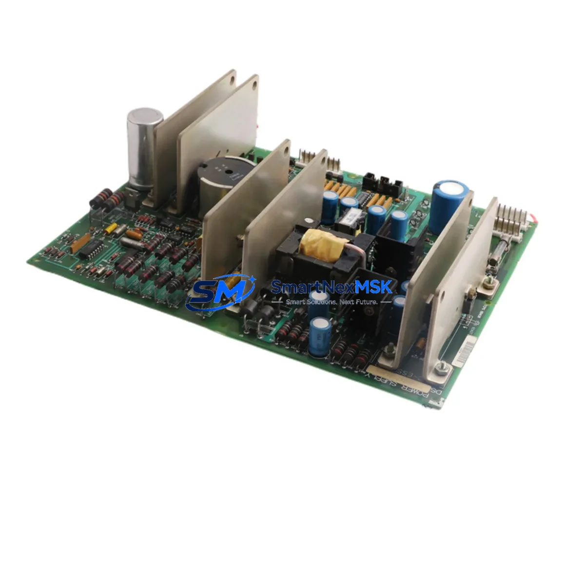
GE DS200TCPSG1AME Retrofit-Ready Power Supply for Mark V Speedtronic Control Systems
The GE DS200TCPSG1AME is a TCP/SG-series power supply board engineered for the GE Mark V Speedtronic turbine control platform — one of the most widely deployed gas turbine control systems in power generation, oil & gas, and industrial process facilities worldwide. As the Mark V platform approaches end-of-life and OEM support becomes increasingly limited, the DS200TCPSG1AME has become a critical retrofit and replacement component for engineers tasked with extending the operational life of existing control cabinets without a full system overhaul.
This board supplies regulated DC power to the Mark V core processor cards and I/O modules housed within the standard Mark V TCPS rack assembly. It interfaces directly with the backplane bus, distributing power to adjacent boards including the DS200TCQCG1A (QC card), DS200TCEAG1B (EA card), and DS200TCDAG1A (DA card). When replacing a failed or degraded DS200TCPSG1AME, engineers must verify that the replacement board’s firmware revision is compatible with the existing DS200TCPAG1A processor card to avoid initialization faults during restart.
Before installation, confirm the incoming AC supply voltage matches the board’s rated input range. The Mark V cabinet typically receives 120 VAC or 240 VAC depending on site configuration, and the DS200TCPSG1AME must be matched accordingly. Terminal block wiring on the power input side should be inspected for corrosion or loose connections — a common cause of intermittent power faults in aging cabinets. The output DC rails (typically +5 VDC, +15 VDC, and −15 VDC) should be verified with a calibrated multimeter before powering up the full rack.
Upgrade Compatibility Table
| Parameter | DS200TCPSG1AME (This Unit) | Retrofit Notes |
|---|---|---|
| Platform Compatibility | GE Mark V Speedtronic | Verify rack slot assignment matches original board position |
| Rack / Backplane Interface | TCPS Rack Backplane | Confirm backplane connector pins are undamaged before seating |
| Input Voltage | 120 VAC / 240 VAC (site-dependent) | Match to cabinet AC supply; do not interchange without jumper reconfiguration |
| Output Rails | +5 VDC, ±15 VDC | Measure all rails under load before full system restart |
| Communication Compatibility | Mark V internal bus (ARCNET / serial) | No protocol migration required; board is bus-transparent |
| Replacement for Obsolete P/N | DS200TCPSG1AME (direct) | Cross-reference with DS200TCPSG1A suffix variants if needed |
| Installation Requirement | Cabinet power-off, ESD precautions | Follow GE GEH-6721 maintenance manual procedures |
| Commissioning / Debug | Toolbox ST / Mark V HMI diagnostics | Check power fault alarms in HMI after restart; clear latched faults |
| Warranty | 12-Month Warranty — covers manufacturing defects and functional failure under normal operating conditions | |
Retrofit Planning for Existing Automation Systems
A successful DS200TCPSG1AME retrofit begins well before the replacement board arrives on site. Engineers should conduct a full audit of the Mark V cabinet, documenting the current slot layout, board revisions, and any field modifications made since original commissioning. In many aging installations, the DS200TCQCG1A QC card and DS200TCEAG1B EA card will have accumulated firmware patches that must be preserved during the power supply swap. Since the DS200TCPSG1AME does not store program logic, the replacement itself does not affect the control program — but a power interruption during the swap can trigger watchdog resets on the DS200TCPAG1A processor card, requiring a controlled restart sequence.
For cabinets that also include a DS200TCRAG1A relay output board or a DS200TCDAH1BHD analog I/O board, verify that the replacement power supply’s output current capacity is sufficient to support the full I/O load. Undersized power supplies are a frequent root cause of intermittent I/O faults in expanded Mark V configurations. If the existing cabinet has been upgraded with additional I/O expansion racks, a secondary power supply board may already be present — confirm its health before assuming the primary DS200TCPSG1AME is the sole fault source.
Communication continuity is another key consideration. The Mark V platform typically uses ARCNET for inter-controller communication and RS-232/RS-485 serial links for HMI connectivity. The DS200TCPSG1AME does not directly handle communications, but a power rail instability can cause the DS200TCSCG1A serial communication card to drop its link, resulting in HMI alarm floods. Stabilizing the power supply is therefore a prerequisite for any communication troubleshooting effort. If the site is also planning a migration from the Mark V HMI to a modern SCADA or DCS interface, the power supply retrofit is the ideal first step before introducing new communication hardware.
For sites considering a phased migration toward the GE Mark VIe platform, the DS200TCPSG1AME retrofit buys critical operational time. The Mark VIe uses a different rack architecture and Ethernet-based I/O (IONet), so a full migration will eventually require replacement of the TCPS rack, processor cards, and I/O modules. However, keeping the Mark V running reliably with a fresh DS200TCPSG1AME allows engineering teams to plan the migration on their own schedule rather than under emergency conditions.
Downtime Control During System Migration
Minimizing unplanned downtime is the primary concern for any Mark V power supply replacement. The recommended approach is to pre-stage the DS200TCPSG1AME replacement board in the control room, perform a full visual and electrical inspection, and confirm the output voltages on the bench before the scheduled maintenance window. This eliminates the risk of discovering a DOA board during a live outage.
During the swap, the original control program stored on the DS200TCPAG1A processor card’s non-volatile memory is not affected by removing the power supply board. However, any unsaved HMI setpoint changes or runtime parameter adjustments will be lost if the processor loses power unexpectedly. Before initiating the swap, operators should capture a full parameter snapshot using the Mark V Toolbox ST software and store it on an external programming cable-connected laptop. The DS200TCPSG1AME replacement can then be completed within a typical 30–60 minute maintenance window, with system restart and HMI verification completing the process.
Post-replacement commissioning should include a systematic check of all power fault alarms on the HMI, verification of I/O module status LEDs across the rack, and a functional test of the turbine control sequence in manual mode before returning to automatic operation. Document the replacement date, board serial number, and output voltage readings in the site maintenance log to support future troubleshooting and warranty claims.
Retrofit Support FAQ
Q1: Is the DS200TCPSG1AME a direct drop-in replacement for all Mark V Speedtronic power supply variants?
The DS200TCPSG1AME is a direct replacement for units with the same base part number. Suffix variants (e.g., AME, BHD) may indicate minor hardware revisions. Confirm the suffix compatibility with your existing rack configuration before installation. In most cases, cross-suffix substitution is acceptable, but verify output voltage specifications match.
Q2: Will replacing the power supply board affect my existing control program or HMI configuration?
No. The DS200TCPSG1AME does not store control logic. Your program resides on the DS200TCPAG1A processor card and will be retained through the swap. However, always back up your program via Toolbox ST before any hardware maintenance as a precaution.
Q3: What wiring checks are required before installing the replacement board?
Inspect all terminal block connections on the AC input side for corrosion, loose screws, or heat damage. Verify that the AC input voltage matches the board’s rated input. Check the backplane connector on the rack for bent or corroded pins. Measure the output DC rails under no-load conditions after installation before powering the full rack.
Q4: What does the 12-month warranty cover, and how is it claimed?
The 12-month warranty covers manufacturing defects and functional failure under normal operating conditions. It does not cover damage caused by incorrect installation, overvoltage, or physical mishandling. To initiate a warranty claim, contact our sales team with the board serial number, purchase date, and a description of the fault. Replacement or repair will be arranged within the warranty period.
© 2026 SMARTNEXMSK. All rights reserved.
Original Source: https://smartnexmsk.com
Contact: sales@smartnexmsk.com | +86 18259474341


