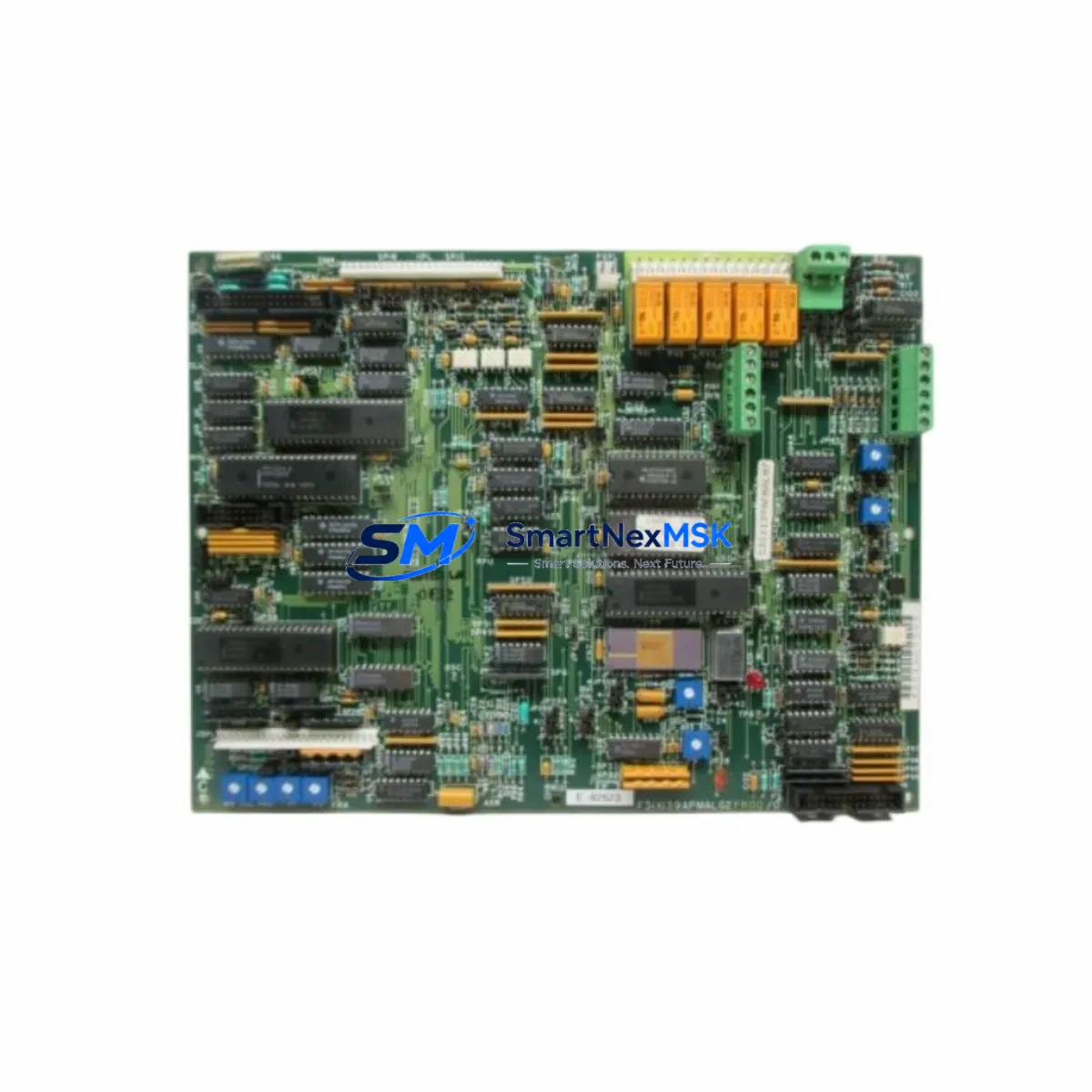
GE F31X139APMALG2FR00 Retrofit-Ready I/O PC Board for Mark VI Speedtronic Control Systems
The GE F31X139APMALG2FR00 is a high-reliability I/O PC Board engineered for the GE Mark VI Speedtronic turbine control platform. As legacy Mark V and early Mark VI installations reach end-of-support milestones, plant engineers and control system integrators increasingly rely on verified replacement boards like the F31X139APMALG2FR00 to sustain operational continuity without committing to a full control system overhaul. This board serves as a direct retrofit solution for aging I/O assemblies, offering a cost-effective path to extend the service life of existing Mark VI cabinets while maintaining full compatibility with the original control architecture.
Whether you are replacing a failed board on an emergency basis, executing a planned outage upgrade, or building a critical spare inventory, the F31X139APMALG2FR00 is pre-tested, firmware-verified, and ready for installation. Each unit undergoes functional validation prior to shipment, and is backed by a 12-month warranty covering manufacturing defects and operational failures under normal service conditions.
Upgrade Compatibility Table
| Parameter | Details |
|---|---|
| Part Number | F31X139APMALG2FR00 |
| OEM Brand | GE (General Electric) |
| Compatible Platform | Mark VI Speedtronic Turbine Control System |
| Board Type | I/O PC Board |
| Replaces / Upgrades | Obsolete Mark V I/O boards; early Mark VI I/O assemblies |
| Backplane Interface | Mark VI standard VME-compatible backplane |
| Communication Compatibility | IONET, Ethernet-based Mark VI I/O network |
| Installation Requirement | Rack-mount into Mark VI I/O enclosure; verify slot addressing |
| Firmware / Software | Compatible with ToolboxST configuration environment |
| Debugging Focus | Module address assignment, I/O signal mapping, HMI tag binding |
| Warranty | 12 Months from shipment date |
| Condition | New / Refurbished-tested available |
Retrofit Planning for Existing Automation Systems
Successful integration of the F31X139APMALG2FR00 into an existing Mark VI Speedtronic system requires careful pre-installation planning. Before removing the legacy board, engineers should document all terminal wiring assignments and verify that the replacement board’s I/O channel configuration matches the original. The Mark VI system uses a distributed I/O architecture where each board occupies a defined slot address on the IONET communication network; incorrect addressing will prevent the controller from recognizing the new module and may trigger system faults.
Power supply capacity is a critical verification step. The Mark VI I/O enclosure is typically fed by a dedicated DC power module — commonly the IS200EPSMG1A or equivalent — and the total current draw of all installed I/O boards must remain within the rated output of the power supply. Adding or replacing boards without recalculating the power budget can result in intermittent resets or permanent damage to the power module.
Backplane seating must be confirmed with the board fully engaged and locking tabs secured. Partial seating is a common cause of communication errors on the IONET bus. After physical installation, the ToolboxST software environment is used to assign the module address, configure I/O signal types, and verify that all analog and digital channels are correctly mapped to the application program variables.
For plants migrating from Mark V to Mark VI, the I/O signal list must be cross-referenced against the new board’s channel specifications. Mark V systems used a different I/O board family — including boards from the DS200 and DS215 series — and direct pin-for-pin compatibility cannot be assumed. Terminal block adapters or rewiring may be required depending on the specific I/O types involved.
HMI integration is another key milestone. After the board is recognized by the controller, HMI screens built on the GE Cimplicity or iFIX SCADA platform must be verified to confirm that all process variable tags are correctly bound to the new I/O addresses. Any tag mismatches will result in stale or missing data on operator displays, which can compromise situational awareness during startup.
Communication link integrity should be validated using the Mark VI diagnostic tools within ToolboxST, confirming that the IONET segment carrying the new board shows no packet loss or CRC errors. In triple-redundant (TMR) configurations, all three I/O boards in the redundant set — typically installed in the R, S, and T controllers — must be updated simultaneously or in a controlled rolling sequence to avoid voting mismatches.
For systems that also include communication interface modules such as the IS200VTURH1BAA or IS200STCIH2A, verify that the updated I/O configuration does not conflict with existing Modbus, Profibus, or OPC-DA data exchange mappings. Rack assemblies incorporating the IS200TREGH1B terminal board should also be inspected for terminal corrosion or loose ferrules before the new I/O board is commissioned.
Downtime Control During System Migration
Minimizing unplanned downtime is the primary operational concern when replacing I/O boards in a live turbine control environment. The recommended approach is to perform the board swap during a scheduled maintenance window, with the turbine in a safe shutdown state and all energy isolation procedures completed per site LOTO protocols.
Before the outage begins, a full backup of the Mark VI application program should be exported from ToolboxST and stored on an offline engineering workstation. This backup preserves all ladder logic, function block diagrams, I/O signal assignments, alarm setpoints, and PID tuning parameters. If the replacement board requires a firmware update, the update package should be staged and validated on a test rack — or confirmed compatible with the installed ToolboxST version — before the maintenance window opens.
During the swap, the original board should be retained as a fallback spare until the replacement has been fully commissioned and the unit has returned to normal operation. Post-installation commissioning should include a loop check of all I/O channels, a functional test of all interlocks and protective trips associated with the replaced board, and a review of the first-out alarm log to confirm no latent faults were introduced during the installation.
For critical applications where continuous control is required, a hot-standby strategy using the Mark VI’s TMR redundancy architecture can allow board replacement on one controller leg while the remaining two legs maintain control authority. This approach eliminates process interruption entirely but requires careful coordination with the control system vendor’s field service guidelines.
Once the unit is back online, monitor the IONET diagnostic counters and I/O health status in ToolboxST for the first 24–48 hours of operation to confirm stable communication and correct signal behavior across all channels.
Retrofit Support FAQ
Q1: Is the F31X139APMALG2FR00 a direct drop-in replacement for the original GE board?
A: Yes, the F31X139APMALG2FR00 is designed as a form-fit-function replacement for the original GE Mark VI I/O PC Board of the same part number. No hardware modifications to the enclosure or backplane are required. However, engineers should verify the installed firmware revision and ToolboxST configuration file compatibility before commissioning, as minor revision differences may require a configuration update.
Q2: What wiring checks are required before installing the replacement board?
A: Prior to installation, inspect all field wiring terminations at the associated terminal board (such as the IS200TREGH1B or equivalent) for tightness, correct ferrule crimping, and absence of corrosion. Verify that the wiring schedule matches the I/O channel assignments documented in the original engineering drawings. Any discrepancies should be resolved before the new board is powered up to prevent signal errors or channel damage.
Q3: Has the board been tested before shipment?
A: Yes. Every F31X139APMALG2FR00 unit is functionally tested prior to shipment using GE Mark VI-compatible test equipment. The test procedure covers power-on self-test, I/O channel continuity, communication interface verification, and firmware integrity check. A test report is available upon request. All units are covered by a 12-month warranty from the date of shipment.
Q4: Can this board be used in a Mark VI TMR (Triple Modular Redundant) configuration?
A: Yes. The F31X139APMALG2FR00 is compatible with both simplex and TMR Mark VI configurations. In a TMR system, the board must be installed in the correct controller leg (R, S, or T) and the module address must match the configuration defined in the ToolboxST project file. It is strongly recommended to update all three legs of a redundant I/O set within the same maintenance window to maintain voting consistency and avoid nuisance trips.
© 2026 SMARTNEXMSK. All rights reserved.
Original Source: https://smartnexmsk.com
Contact: sales@smartnexmsk.com | +86 18259474341


