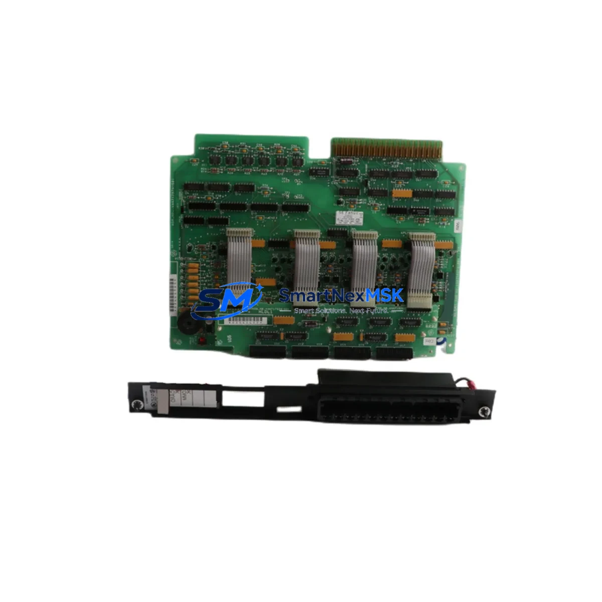
GE IC600BF929 Retrofit-Ready Discrete Output Module for Series Six Control Systems
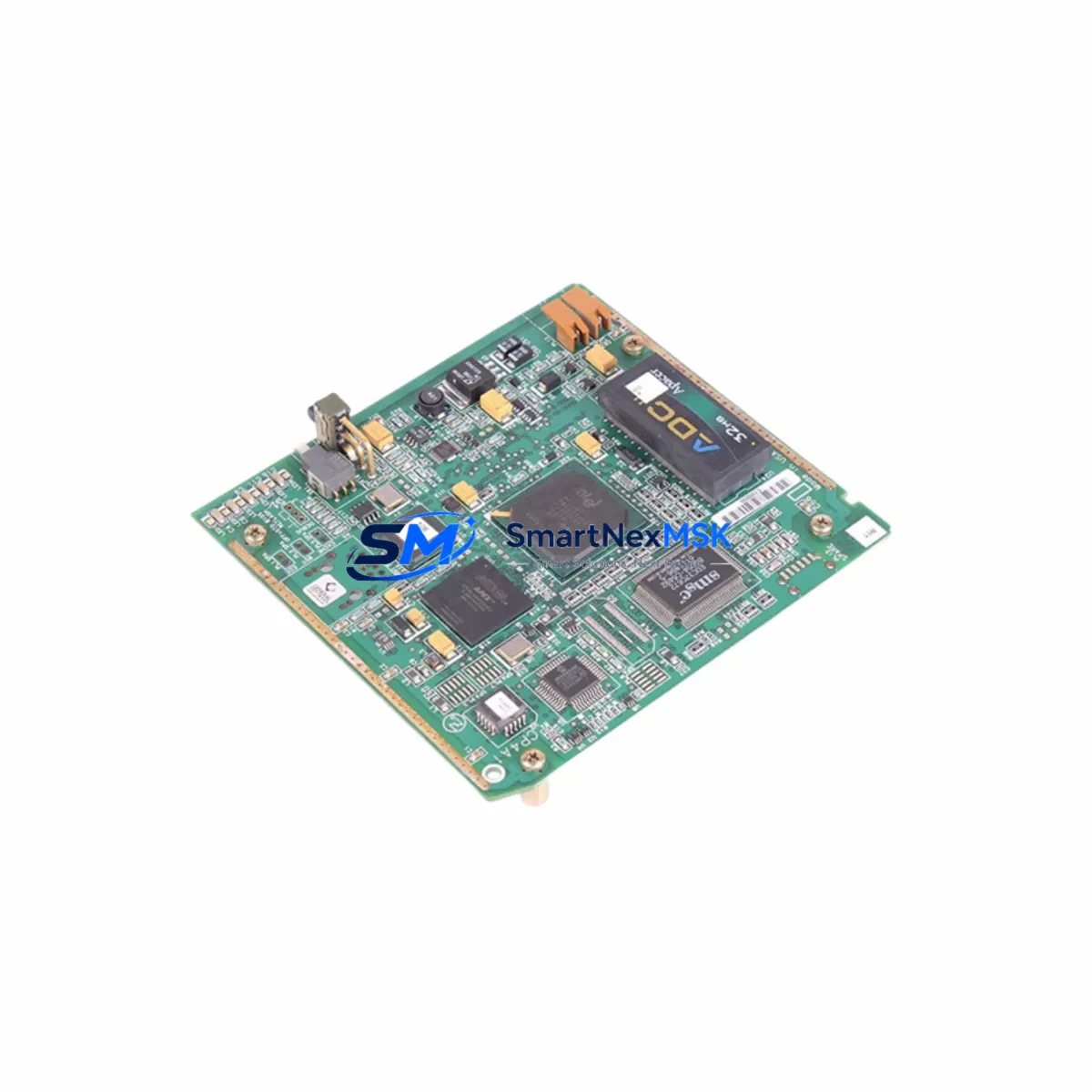
The GE IC600BF929 (also catalogued as IC660FP900K and IC600BF929K) is a discrete output module engineered for the GE Series Six programmable controller platform and the Genius I/O distributed I/O bus architecture. As legacy Series Six systems approach end-of-life and OEM support becomes increasingly scarce, this module has become a critical retrofit component for facilities seeking to extend operational life, reduce unplanned downtime, and defer full system replacement costs.
SMARTNEXMSK maintains verified stock of the IC600BF929 and its functional equivalents, each unit passing pre-shipment functional testing and covered by a 12-month warranty. Whether you are executing a planned control cabinet upgrade, responding to an emergency spare-parts shortage, or migrating from a discontinued I/O network, this module provides a reliable, cost-effective path forward.
Upgrade Compatibility Table
| Parameter | IC600BF929 / IC660FP900K | Retrofit Notes |
|---|---|---|
| Platform Compatibility | GE Series Six, Genius I/O Bus | Verify rack slot assignment and bus address before installation |
| Output Type | Discrete (relay / solid-state, confirm per variant) | Match output sink/source logic with field wiring |
| Backplane Interface | Series Six backplane connector | Confirm IC600CH912 or IC600CH916 chassis compatibility |
| Communication Protocol | Genius Bus (serial token-passing) | Bus address must be set via DIP switch before power-on |
| Power Supply Requirement | +5 VDC backplane; field side per output spec | Verify IC600PS524 or equivalent PSU capacity before swap |
| Installation Format | Rack-mount, Series Six form factor | No mechanical modification required for direct slot replacement |
| Program Compatibility | Ladder logic references I/O address map | Confirm %Q address assignments in Logicmaster 6 or equivalent |
| HMI Integration | Compatible with CIMPLICITY and legacy GE View screens | Update I/O tag references if module address changes |
| Replacement SKUs | IC600BF929, IC660FP900K, IC600BF929K | All three part numbers are functionally interchangeable |
| Warranty | 12-Month Warranty — all units pre-shipment tested | |
Retrofit Planning for Existing Automation Systems
Successful integration of the IC600BF929 into an aging control system begins well before the module arrives on site. Engineers should start by auditing the existing IC600CH912 or IC600CH916 rack chassis to confirm available slot positions and backplane integrity. The IC600PS524 power supply module must be evaluated for remaining capacity — adding or replacing output modules can shift the total backplane current draw, and an undersized PSU is a common cause of intermittent faults after retrofit.
Terminal wiring is the next critical checkpoint. The IC600BF929 uses a field-side terminal block that must be matched against the existing wiring schedule. In many older installations, wire labeling has degraded or been modified without documentation updates; a point-by-point continuity check against the original I/O list is strongly recommended before energizing the replacement module. If the control cabinet also houses a Genius Bus Controller (IC660BBA020 or IC660BBA100), confirm that the bus scan rate and block transfer configuration remain consistent with the new module’s address assignment.
For facilities running Logicmaster 6 programming software, the %Q output address map should be reviewed to ensure the replacement module occupies the same logical slot. If the physical slot position changes — for example, due to rack consolidation during a cabinet upgrade — the program logic must be updated accordingly and a full I/O forcing test performed offline before live commissioning. Sites that have migrated to Proficy Machine Edition for Series 90 or VersaMax platforms should note that the IC600BF929 is not directly compatible with those architectures; a protocol gateway or a phased migration using an IC693CMM321 communications module may be required to bridge legacy Genius I/O segments to a newer CPU backplane.
When the retrofit scope extends beyond a single module swap to a full I/O expansion, consider whether the existing rack has sufficient slots or whether an additional IC600CH916 expansion chassis is needed. I/O expansion in Series Six environments also requires attention to the Genius Bus segment length and termination resistor placement — an improperly terminated bus is a frequent source of communication errors that can be misdiagnosed as module failure. Pairing the IC600BF929 with a verified IC660CBB902 Genius Bus cable assembly and correct 75-ohm termination ensures signal integrity across the segment.
For sites where the HMI layer runs on legacy CIMPLICITY HMI or a third-party SCADA connected via SNP or SRTP protocol, verify that the I/O point database reflects the updated module configuration. Tag mismatches between the PLC I/O map and the HMI screen objects are a common post-retrofit issue that can trigger nuisance alarms or mask real process faults during the initial commissioning period.
Downtime Control During System Migration
Minimizing production interruption during a Series Six output module replacement requires a structured hot-swap or planned-outage strategy. Where the process permits, use the Genius Bus’s inherent fault isolation capability — a single module fault on the Genius Bus does not necessarily take down the entire I/O segment, allowing adjacent modules such as the IC660BBD024 discrete input block or analog output modules to continue operating while the faulted output block is replaced.
Before removing the IC600BF929 or its predecessor, force all associated outputs to a safe state through the PLC program or via the Logicmaster 6 I/O forcing table. Document the current DIP switch settings for bus address and configuration — these must be replicated exactly on the replacement unit. If the replacement module is the IC660FP900K variant, confirm that the firmware revision is compatible with the installed Genius Bus Controller firmware; mismatched firmware revisions can cause block initialization failures that appear as hardware faults.
After physical installation, perform a controlled power-up sequence: energize the backplane first, confirm the module’s status LED sequence, then re-enable the Genius Bus scan. Verify each output point individually using the I/O forcing function before returning the system to automatic mode. This structured commissioning approach, combined with a pre-tested replacement unit from SMARTNEXMSK’s inventory, typically reduces total planned outage time to under two hours for a single-module swap in a well-documented system.
For emergency unplanned replacements, SMARTNEXMSK’s in-stock position on IC600BF929, IC660FP900K, and IC600BF929K means same-day dispatch is available for urgent orders, reducing the window between fault detection and system restoration.
Retrofit Support FAQ
Q1: Is the IC660FP900K a direct drop-in replacement for the IC600BF929?
Yes. The IC660FP900K and IC600BF929K are functionally equivalent to the IC600BF929 and are interchangeable in the same rack slot without hardware modification. The primary difference is the catalog number revision; all three share the same backplane connector, bus protocol, and output circuit design. Confirm the DIP switch address settings match the original module before installation.
Q2: What pre-shipment testing does SMARTNEXMSK perform on the IC600BF929?
Every unit undergoes functional output verification, backplane connector inspection, and bus communication initialization testing before dispatch. Units that fail any test stage are quarantined and not shipped. All shipped units are covered by a 12-month warranty from the date of delivery.
Q3: Can the IC600BF929 be used in a mixed Series Six and Genius I/O distributed rack configuration?
Yes, provided the Genius Bus Controller (such as the IC660BBA020) is correctly configured for the mixed topology. The IC600BF929 operates as a standard Genius Bus block and is compatible with both local rack and remote drop configurations. Bus address assignment via DIP switch must be unique across the entire Genius Bus segment.
Q4: What should I verify regarding wiring compatibility before installing the replacement module?
Confirm the field-side terminal block wiring against the original I/O schedule, checking wire gauge, terminal torque specifications, and output load current against the module’s rated output capacity. Verify that the field power supply voltage matches the module’s output circuit requirements. If the original module used a removable terminal block, confirm the replacement unit includes a compatible terminal block or that the existing one can be transferred.
© 2026 SMARTNEXMSK. All rights reserved.
Original Source: https://smartnexmsk.com
Contact: sales@smartnexmsk.com | +86 18259474341