GE IC610CHS134 Spare for Series 90-20 Automation: Spare Replacement & Industrial Downtime Risk Control
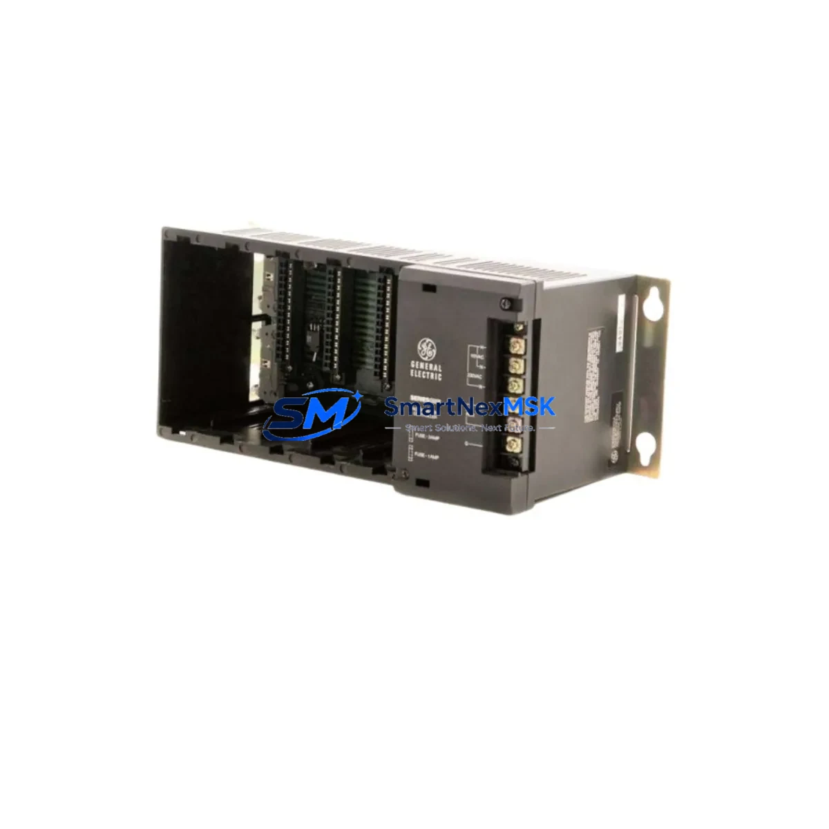
The GE IC610CHS134 is a chassis-mounted power supply module designed for the Series 90-20 programmable logic controller platform. In industrial maintenance environments — from discrete manufacturing lines to process control panels — this module serves as the backbone of the PLC rack, delivering regulated DC power to all installed I/O and CPU modules. When this component fails or degrades, the entire control rack loses operational integrity, making rapid spare replacement a critical priority for maintenance engineers and plant operations teams.
Sourced as an original GE spare, the IC610CHS134 is verified for compatibility with the Series 90-20 chassis family. Each unit undergoes functional testing prior to shipment, ensuring that the module powers up correctly, maintains stable output voltage under load, and meets the electrical specifications required for continuous industrial operation. A 12-month warranty is included with every unit, covering defects in materials and workmanship under normal operating conditions.
Spare Maintenance Table
| Parameter | Specification / Detail |
|---|---|
| Part Number / SKU | IC610CHS134 |
| Brand | GE (General Electric Automation) |
| Series | Series 90-20 PLC |
| Module Type | Chassis Power Supply Module |
| Input Voltage | 85–264 VAC, 47–63 Hz (universal input) |
| Output Voltage | +5 VDC, +24 VDC (backplane regulated) |
| Chassis Compatibility | Series 90-20 5-slot and 9-slot chassis |
| Installation | DIN rail / panel mount, tool-free module insertion |
| Operating Temperature | 0°C to 60°C (32°F to 140°F) |
| Relative Humidity | 5% to 95% non-condensing |
| Protection Class | IP20 (panel-mounted enclosure required) |
| Certifications | UL, CE (original GE production) |
| Condition | Original spare, tested before shipment |
| Warranty | 12 months from date of shipment |
| Lead Time | In stock — ships within 1–3 business days |
| Origin | United States |
Maintenance Planning for Continuous Operation
When replacing the IC610CHS134 in a Series 90-20 rack, a thorough maintenance inspection of the surrounding control cabinet is strongly recommended. Power supply failures in PLC systems are rarely isolated events — they often indicate broader issues with input power quality, grounding, or thermal management within the enclosure.
Begin by verifying the incoming AC supply voltage and checking the IC610CHS101 or IC610CHS105 chassis base for signs of physical damage, corrosion on the backplane connectors, or loose module seating. Inspect the IC610MDL175 discrete input module and IC610MDL140 output module for any blown fuse indicators or LED fault states — these I/O modules share the backplane power bus and can be affected by power transients that caused the original supply failure.
Check the IC610CPU105 CPU module for battery backup status and memory integrity. A power supply replacement is an ideal time to verify that the CPU’s program memory is intact and that the RTC (real-time clock) battery is within its service life. If the system uses the IC610MDL230 analog input module, recalibration after power restoration may be required.
For systems with communications requirements, inspect the IC610BAS010 base controller and any attached IC610MDL120 relay output modules. Relay contacts should be checked for wear, especially in high-cycle applications. Terminal blocks and field wiring connections throughout the cabinet should be re-torqued to specification — loose terminals are a common secondary cause of intermittent faults following a power supply event.
If the control cabinet includes signal isolators between field instruments and the PLC I/O, verify that these isolators are operating within their rated input/output ranges. Surge protection devices on the incoming power feed and on field signal cables should also be inspected and replaced if they have absorbed a transient event. Maintaining a documented spare parts inventory that includes at least one IC610CHS134, a spare CPU module, and a set of commonly used I/O modules is a best practice for any facility running Series 90-20 systems in critical process applications.
Site Replacement Workflow
Replacing the IC610CHS134 in the field is a straightforward procedure when the correct spare is on hand. Begin by placing the PLC system in a safe, controlled shutdown state — coordinate with operations to ensure that all field devices are in a safe position before de-energizing the rack. Document the current program version and I/O configuration before removing any modules.
De-energize the cabinet and allow the capacitors in the power supply to discharge (typically 30–60 seconds). Remove the faulty IC610CHS134 by releasing the module latch and sliding it out of the chassis slot. Inspect the backplane connector pins for damage or contamination before inserting the replacement unit. Seat the new module firmly until the latch engages, then restore power and verify that all module status LEDs indicate normal operation.
For facilities transitioning away from older Series 90-20 hardware, the IC610CHS134 provides a direct, pin-compatible replacement that avoids the need for chassis or wiring modifications. This makes it the preferred choice for extending the operational life of legacy control systems without the cost and downtime associated with a full platform migration. Compatibility with both 5-slot and 9-slot chassis configurations means a single spare SKU can cover multiple rack variants across a plant.
After replacement, perform a full I/O scan and verify communications with any connected HMI panels or SCADA systems. Log the replacement in the maintenance management system with the date, technician ID, and the serial number of the replaced unit for traceability.
Spare Parts Support FAQ
Q1: Is the IC610CHS134 compatible with both 5-slot and 9-slot Series 90-20 chassis?
Yes. The IC610CHS134 is designed for use across the Series 90-20 chassis family, including both 5-slot and 9-slot configurations. Always verify the chassis model number on the nameplate before installation to confirm slot count and backplane connector alignment.
Q2: What testing is performed before shipment?
Each IC610CHS134 unit is functionally tested prior to shipment. Testing includes power-on verification, output voltage measurement under load, and visual inspection of the module housing and connector pins. Units that do not meet specification are not shipped.
Q3: What does the 12-month warranty cover?
The 12-month warranty covers defects in materials and workmanship under normal operating conditions. It does not cover damage resulting from incorrect installation, overvoltage events, physical impact, or use outside the module’s rated environmental specifications. Warranty claims are processed through our sales team at sales@smartnexmsk.com.
Q4: How should I manage IC610CHS134 inventory for a multi-site facility?
For facilities operating multiple Series 90-20 systems, we recommend maintaining a minimum of one IC610CHS134 per site as a critical spare. For high-availability applications, a two-unit buffer per site is advisable. Long-term supply agreements are available for procurement teams requiring guaranteed stock allocation across extended maintenance cycles.
© 2026 SMARTNEXMSK. All rights reserved.
Original Source: https://smartnexmsk.com
Contact: sales@smartnexmsk.com | +86 18259474341


