GE IC610MDL106 Retrofit-Ready Discrete Input Module for Series One Control Systems
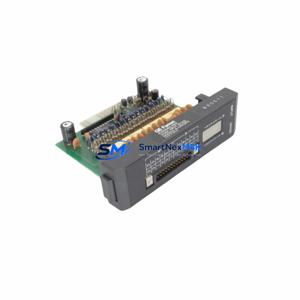
The GE IC610MDL106 is a 16-point, 120VAC discrete input module originally designed for the GE Series One programmable logic controller platform. As legacy Series One systems approach end-of-life and spare parts become increasingly scarce, the IC610MDL106 remains one of the most sought-after replacement components for engineers tasked with keeping aging production lines operational. Whether you are managing a planned control system upgrade or responding to an unplanned module failure, sourcing a verified, tested IC610MDL106 is often the fastest path to restoring machine availability without committing to a full PLC migration.
This module accepts 16 discrete AC input signals at 120VAC nominal, making it directly compatible with field wiring already installed for the original Series One rack. The IC610MDL106 mounts into the standard Series One baseplate — including the IC610BAS010, IC610BAS020, and IC610BAS030 rack configurations — and communicates with the Series One CPU through the backplane bus without requiring any hardware modification. For facilities running the IC610CPU105 or IC610CPU106 central processing units, the IC610MDL106 integrates seamlessly into the existing program logic, preserving all rung-level input references and I/O address assignments that were configured in the original application.
Before installing a replacement IC610MDL106, engineers should verify several critical parameters to ensure a smooth retrofit. First, confirm that the rack’s power supply — typically the IC610PSA100 or IC610PSA101 — has sufficient current capacity to support the additional module load. Second, review the terminal block wiring diagram against the original field wiring schedule to confirm that all 16 input channels are correctly landed and that the common neutral is properly shared. Third, validate the module slot address assignment in the CPU configuration table, as an incorrect slot address will cause the CPU to flag an I/O configuration fault and halt the control program. Fourth, if the facility uses a Series One programming panel or a PC-based programmer running the original Series One ladder logic software, upload and archive the current program before swapping the module to protect against accidental program loss during power cycling.
For sites that are using the IC610MDL106 replacement as a stepping stone toward a broader control system modernization, it is worth noting that the Series One platform shares a common migration path with the GE 90-30 series. Many facilities choose to replace individual failed modules — such as the IC610MDL106 for discrete inputs, the IC610MDL140 or IC610MDL141 for discrete outputs, and the IC610ALG160 for analog input functions — while simultaneously planning a phased transition to a GE Fanuc 90-30 rack, which offers expanded I/O density, Ethernet communications via the IC693CMM321 communications module, and compatibility with modern HMI platforms running Proficy iFIX or Cimplicity. During this transition period, maintaining a verified stock of Series One modules ensures that the legacy system remains operational while the new control architecture is being commissioned in parallel.
Communication protocol migration is another key consideration during Series One retrofit projects. The original Series One platform relies on a proprietary backplane communication scheme and, in networked installations, may use GE’s legacy Genius bus via the IC610MDL175 Genius bus interface module. When upgrading to a 90-30 or RX3i platform, engineers must plan for the replacement of the Genius bus interface with an IC693BEM331 or equivalent module, and update the HMI communication drivers accordingly. Preserving the original Genius field device wiring while migrating the controller-side interface is a common strategy that minimizes field rewiring costs and reduces overall downtime during the cutover.
Upgrade Compatibility Table
| Parameter | IC610MDL106 (Original / Replacement) | Notes |
|---|---|---|
| Input Type | 16-Point Discrete AC Input, 120VAC | Direct drop-in replacement; no field wiring changes required |
| Rack Compatibility | IC610BAS010 / IC610BAS020 / IC610BAS030 | Fits all standard Series One baseplates |
| CPU Compatibility | IC610CPU105 / IC610CPU106 | Backplane communication fully compatible; no firmware update required |
| Power Supply Requirement | Verify IC610PSA100 / IC610PSA101 current budget | Confirm available current margin before installation |
| I/O Address Assignment | Slot-based addressing per CPU configuration table | Verify slot address matches original configuration to avoid I/O fault |
| Communication Interface | Series One proprietary backplane bus | No protocol conversion required for like-for-like replacement |
| Replacement Recommendation | Direct replacement for failed or end-of-life IC610MDL106 | Suitable for emergency repair and planned maintenance stock |
| Commissioning Requirement | Program upload/archive before swap; verify I/O map post-installation | Force-test all 16 input channels before returning to auto mode |
| Warranty | 12-Month Warranty | Covers manufacturing defects; includes pre-shipment functional test |
Retrofit Planning for Existing Automation Systems
A successful IC610MDL106 retrofit begins with a thorough audit of the existing Series One control cabinet. Start by documenting the current rack layout — recording the module type, slot position, and I/O address for every module installed in the IC610BAS010 or IC610BAS020 baseplate. This audit should capture not only the discrete input modules but also any discrete output modules such as the IC610MDL120 or IC610MDL121, analog I/O modules, and the power supply configuration. Having a complete rack map on hand before beginning any replacement work eliminates guesswork during the installation and significantly reduces the risk of introducing an I/O addressing conflict.
Terminal block wiring is one of the most common sources of delay during a module swap. The IC610MDL106 uses a removable terminal block that, in many installations, has been in service for a decade or more. Before removing the old module, photograph the terminal block wiring from multiple angles and cross-reference against the original wiring schedule. If the terminal block shows signs of corrosion, heat damage, or loose terminations, this is an ideal opportunity to replace it with a new block and re-terminate the field wires to current standards. Ensuring that all 16 input channels and the AC common are correctly landed before powering up the replacement module will prevent nuisance faults and protect the new module from damage caused by miswiring.
For facilities that are simultaneously upgrading their HMI infrastructure, the IC610MDL106 replacement can be coordinated with a migration from an older operator panel to a modern touchscreen HMI. During this transition, it is important to verify that the HMI communication driver — whether connecting via a serial port to the Series One CPU or through a protocol converter — correctly maps the input status bits from the IC610MDL106 to the corresponding HMI display elements. Updating the HMI tag database to reflect any changes in I/O addressing made during the retrofit will prevent display errors and alarm mismatches that can confuse operators during the initial post-commissioning period.
If the retrofit scope includes expanding the I/O count beyond what the existing Series One rack can accommodate, engineers should evaluate the addition of a second rack connected via the IC610MDL175 I/O expansion interface, or consider migrating the expanded I/O to a GE 90-30 remote I/O drop using the IC693CHS391 expansion chassis. Either approach allows the facility to preserve the existing Series One CPU and program logic while adding the I/O capacity needed to support new machine functions or process monitoring requirements.
Downtime Control During System Migration
Minimizing unplanned downtime is the primary objective of any Series One retrofit project. When replacing the IC610MDL106 in a live production environment, the recommended approach is to pre-stage the replacement module, verify its physical condition and firmware compatibility, and schedule the swap during a planned maintenance window rather than responding reactively to a module failure. Pre-staging includes confirming that the replacement module’s hardware revision is compatible with the installed CPU version, and that the terminal block configuration matches the field wiring schedule.
Before initiating the module swap, place the Series One CPU in Stop mode and use the programming software to force all outputs to their safe state. This step protects downstream equipment — including actuators, solenoid valves, and motor starters — from unexpected activation during the module replacement. Once the CPU is in Stop mode, remove the failed IC610MDL106, install the replacement module in the same slot, and verify that the module’s status LED illuminates correctly after power is restored. Do not return the CPU to Run mode until all 16 input channels have been individually verified using the programming software’s I/O forcing function or a handheld field tester.
For critical processes where even a brief Stop-mode interruption is unacceptable, consider implementing a hot-standby strategy using a second Series One rack pre-loaded with a verified copy of the application program. This approach allows the standby system to assume control within seconds of a module failure, preserving process continuity while the primary rack is repaired. After the primary rack is restored and verified, a controlled switchback can be performed during the next scheduled production break. Maintaining a documented switchover procedure and training operators on the manual intervention steps required during a switchover event are essential components of a robust downtime control strategy.
Retrofit Support FAQ
Q1: Is the IC610MDL106 a direct drop-in replacement for the original module, or are wiring modifications required?
The IC610MDL106 replacement is a direct drop-in for the original module. The terminal block pinout, backplane connector, and I/O addressing scheme are identical to the factory-original part. No field wiring modifications are required, provided that the replacement module is installed in the same rack slot as the original. After installation, verify the I/O address assignment in the CPU configuration table and force-test all 16 input channels before returning the system to automatic operation.
Q2: What commissioning steps are required after installing a replacement IC610MDL106?
After installing the replacement module, restore power to the rack and confirm that the module’s status LED indicates normal operation. Using the Series One programming software, go online with the CPU and verify that all 16 input channels are correctly mapped in the I/O configuration table. Force each input channel individually and confirm that the corresponding rung in the ladder logic responds correctly. Check the CPU fault table for any I/O configuration errors and clear any latched faults before returning the CPU to Run mode. Document the commissioning results and retain the test record for maintenance file purposes.
Q3: Can the IC610MDL106 be used in a mixed-module rack alongside newer GE 90-30 modules?
No. The IC610MDL106 is designed exclusively for the GE Series One backplane and is not physically or electrically compatible with the GE 90-30 IC693 series rack. The two platforms use different backplane bus architectures, connector configurations, and power distribution schemes. If you are migrating from Series One to 90-30, the IC610MDL106 must be replaced with the appropriate IC693MDL series discrete input module, and the field wiring must be re-terminated to the new module’s terminal block. Our technical team can assist with identifying the correct 90-30 replacement module based on your specific I/O requirements.
Q4: What does the 12-month warranty cover, and is pre-shipment testing performed?
Every IC610MDL106 unit is functionally tested prior to shipment to verify that all 16 input channels respond correctly to 120VAC input signals and that the backplane communication interface operates within specification. The 12-month warranty covers manufacturing defects and functional failures under normal operating conditions. It does not cover damage resulting from miswiring, overvoltage, physical impact, or installation in an incompatible rack. Warranty claims are processed promptly, and replacement units are dispatched within 2 business days of claim approval to minimize production impact.
© 2026 SMARTNEXMSK. All rights reserved.
Original Source: https://smartnexmsk.com
Contact: sales@smartnexmsk.com | +86 18259474341


