GE IC670GBI102 Retrofit-Ready Genius Bus Interface Unit for Series 90 Micro Control Systems
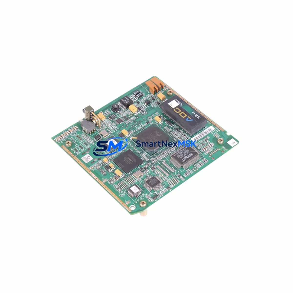
The GE IC670GBI102 is a Genius Bus Interface Unit (BIU) designed for use within the GE Series 90 Micro PLC platform. As legacy automation systems face end-of-life pressures, the IC670GBI102 has become a critical component in retrofit projects, discontinued-part replacements, and control cabinet upgrades across manufacturing, utilities, and process industries. SMARTNEXMSK maintains verified in-stock inventory of the IC670GBI102, fully tested and backed by a 12-month warranty, enabling engineers to execute system migrations with confidence and minimal disruption.
The IC670GBI102 serves as the communication bridge between the Series 90 Micro CPU and field-level Genius I/O blocks distributed across the plant floor. In retrofit scenarios, this module is frequently required when the original BIU has failed, when a plant is expanding its Genius bus segment, or when a facility is consolidating multiple legacy control nodes onto a modernized rack architecture. Before installation, engineers must verify the Genius bus load capacity, confirm the bus address DIP switch settings match the existing network map, and ensure the host CPU — typically an IC693CPU311, IC693CPU321, or IC693CPU341 — is running firmware compatible with the IC670GBI102’s bus protocol revision.
Upgrade Compatibility Table
| Parameter | IC670GBI102 Specification | Retrofit Notes |
|---|---|---|
| Platform | GE Series 90 Micro | Compatible with IC670 rack family |
| Bus Type | Genius Bus (Serial, 153.6 kbps) | Verify bus termination resistors at both ends |
| Bus Address | Configurable via DIP switch (0–31) | Must not conflict with existing Genius block addresses |
| Power Requirement | 5 VDC from backplane (IC670PWR101 or IC670PWR102) | Confirm power supply capacity before adding module |
| Backplane Interface | IC670 5-slot or 10-slot rack | Slot position must be defined in hardware configuration |
| Communication Compatibility | Genius Bus protocol, Series 90 Micro CPU | Not directly compatible with Profibus or DeviceNet without gateway |
| Replacement Candidates | IC670GBI001, IC670GBI101 | Verify firmware revision and bus load before substitution |
| Programming Tool | Logicmaster 90 Micro or VersaPro | Hardware configuration must reflect BIU slot assignment |
| Commissioning Check | Bus OK LED, block status in CPU diagnostics | Confirm all Genius blocks report online after power-up |
| Warranty | 12-Month Warranty — All units tested prior to shipment | |
Retrofit Planning for Existing Automation Systems
Integrating the IC670GBI102 into an existing Series 90 Micro system requires a structured approach to avoid bus conflicts and unplanned downtime. The retrofit process typically begins with a full audit of the existing Genius bus segment: documenting each connected Genius I/O block — such as IC670MDL640 discrete output modules, IC670ALG230 analog input modules, and IC670MDL730 relay output modules — along with their assigned bus addresses and current load contribution. The IC670GBI102 adds to the total bus load, so the engineer must confirm the IC670PWR101 or IC670PWR102 power supply has sufficient 5 VDC capacity to support the additional module without triggering an undervoltage fault.
Terminal wiring for the Genius bus cable must follow the shielded twisted-pair specification, with the shield grounded at one end only to prevent ground loops. If the existing bus cable is aging or shows impedance irregularities, replacement with a new Belden 9463 or equivalent cable is recommended before commissioning the IC670GBI102. The bus termination resistors — typically 100 Ω at each physical end of the Genius bus — must remain in place and must not be duplicated at intermediate nodes.
In the hardware configuration tool (Logicmaster 90 Micro or VersaPro), the IC670GBI102 must be assigned to the correct rack slot. The CPU — whether an IC693CPU311, IC693CPU321, or IC693CPU341 — must have its hardware configuration updated and downloaded before the BIU will communicate with the bus. If the plant is migrating from an older IC670GBI001 or IC670GBI101, the replacement is generally transparent at the program level, but the hardware configuration file must be updated to reflect the new module revision to avoid a configuration mismatch fault on startup.
For facilities upgrading from a standalone Series 90 Micro to a networked architecture, the IC670GBI102 can coexist with an IC693CMM311 or IC693CMM321 communications module installed in the main IC693 rack, allowing the Genius bus field devices to remain in service while the host controller is upgraded. HMI screens connected via SNP or SNP-X protocol to the Series 90 Micro CPU should be verified for tag address compatibility after any hardware configuration change, as slot reassignments can shift the reference addresses of I/O points mapped in the HMI project.
Downtime Control During System Migration
Minimizing production downtime during a Genius bus retrofit requires careful pre-staging and a disciplined cutover sequence. Before the maintenance window opens, the IC670GBI102 should be pre-configured with the correct bus address DIP switch setting, verified against the existing network map, and bench-tested using a spare IC670 rack if available. The replacement module should be powered up in isolation to confirm the Bus OK LED illuminates and no fault codes are present before it is installed in the live system.
During the cutover, the recommended sequence is: (1) place the CPU in Stop mode and record all current I/O states for reference; (2) remove the failed or legacy BIU from the rack; (3) install the IC670GBI102 in the same slot position; (4) power up the rack and confirm the module seats correctly on the backplane; (5) transition the CPU to Run mode and monitor the Genius bus status in the CPU diagnostics screen. If the bus does not recover within 30 seconds, check the bus address conflict log and verify termination resistor continuity.
To protect the original program logic, a full backup of the CPU program — including ladder logic, hardware configuration, and data tables — should be saved to a programming device running Logicmaster 90 Micro or VersaPro before any hardware change is made. This backup ensures that if the CPU loses its program during a power cycle, the original logic can be restored in minutes rather than hours. Field control continuity is maintained by keeping the Genius I/O blocks powered throughout the swap, as the blocks retain their last output states during a brief bus interruption, reducing the risk of uncontrolled process changes during the module exchange.
Retrofit Support FAQ
Q: Is the IC670GBI102 a direct drop-in replacement for the IC670GBI001?
A: In most applications, yes. The IC670GBI102 occupies the same rack slot, uses the same Genius bus wiring, and is recognized by the same CPU firmware. However, the hardware configuration file must be updated in Logicmaster 90 Micro or VersaPro to reference the IC670GBI102 module revision. Failure to update the configuration will result in a module mismatch fault. SMARTNEXMSK recommends verifying the CPU firmware version and hardware configuration revision before installation.
Q: What commissioning steps are required after installing the IC670GBI102?
A: After physical installation, download the updated hardware configuration to the CPU, then transition to Run mode. Monitor the Genius bus status display in the CPU diagnostics to confirm all blocks report online. Verify that the Bus OK LED on the IC670GBI102 is solid green. Check HMI screens for any I/O address discrepancies and confirm that all analog and discrete I/O points are reading correctly before returning the system to automatic operation.
Q: How do I verify wiring compatibility when replacing the BIU on an aging Genius bus segment?
A: Use a digital multimeter to measure the DC resistance between the two Genius bus conductors at the BIU terminal with the bus cable disconnected. The resistance should be approximately 50 Ω if both termination resistors (100 Ω each) are in place and the cable is intact. Values significantly above or below this indicate a wiring fault, a missing terminator, or cable damage that should be resolved before the new IC670GBI102 is commissioned.
Q: What warranty and pre-shipment testing does SMARTNEXMSK provide for the IC670GBI102?
A: Every IC670GBI102 unit shipped by SMARTNEXMSK undergoes functional testing prior to dispatch, including bus communication verification and backplane interface checks. All units are covered by a 12-month warranty against manufacturing defects and functional failures. In the event of a warranty claim, SMARTNEXMSK provides advance replacement support to minimize production impact. Contact sales@smartnexmsk.com or +86 18259474341 for warranty registration and support.
© 2026 SMARTNEXMSK. All rights reserved.
Original Source: https://smartnexmsk.com
Contact: sales@smartnexmsk.com | +86 18259474341