GE IC693BEM331 Retrofit-Ready Genius Bus Controller for Series 90-30 Control Systems
The GE IC693BEM331 is a Genius Bus Controller module designed for GE Series 90-30 programmable logic controller systems. As legacy Series 90-30 installations reach end-of-support milestones and OEM spare parts become increasingly scarce, the IC693BEM331 remains one of the most sought-after retrofit components for engineers tasked with sustaining distributed I/O networks built on the Genius bus architecture. SMARTNEXMSK maintains verified stock of the IC693BEM331, fully tested and backed by a 12-month warranty, to support planned upgrades and emergency replacement scenarios alike.
The IC693BEM331 occupies a single slot in the IC693CHS391 or IC693CHS397 baseplate and interfaces directly with the Series 90-30 CPU — including the IC693CPU364, IC693CPU374, and IC693CPU374 — via the rack backplane. It manages all Genius bus communications, coordinating up to 32 Genius bus devices per bus controller, including GE Genius I/O blocks, distributed analog modules, and remote terminal units. When replacing a failed or end-of-life IC693BEM331, engineers must verify the bus controller’s configured bus address, the number of active Genius devices on the segment, and the scan rate settings stored in the Logicmaster 90 or Proficy Machine Edition project file before swapping the module.
Upgrade Compatibility Table
| Parameter | IC693BEM331 Specification | Retrofit Notes |
|---|---|---|
| Compatible Rack | IC693CHS391 (5-slot), IC693CHS397 (10-slot) | Verify slot availability; module occupies 1 slot |
| Backplane Interface | Series 90-30 parallel backplane | Not compatible with Series 90-70 or PACSystems RX3i backplanes |
| Bus Protocol | GE Genius Bus (serial, 153.6 kbps) | Confirm bus termination resistors at both ends of the Genius cable |
| Max Genius Devices | 32 per bus controller | Audit existing device count before replacement |
| Power Consumption | Supplied via backplane (5 VDC) | Verify IC693PWR321 or IC693PWR330 power supply capacity |
| Programming Tool | Logicmaster 90-30 / Proficy Machine Edition | Back up existing program and hardware configuration before replacement |
| Firmware | Embedded; no field upgrade required | Confirm firmware revision matches project expectations if using advanced features |
| Replacement Path | Direct drop-in for IC693BEM331 (same revision) | Cross-revision compatibility: verify with GE/Emerson documentation |
| Commissioning | Bus address set via software configuration | Match bus address to original module configuration in PME hardware tree |
| Warranty | 12-Month Warranty — all units tested prior to shipment | |
Retrofit Planning for Existing Automation Systems
A successful IC693BEM331 retrofit begins well before the module arrives on-site. The first step is a full audit of the existing Series 90-30 rack configuration. Document every module installed in the IC693CHS391 or IC693CHS397 chassis — including the CPU module (IC693CPU364 or IC693CPU374), the power supply (IC693PWR321 or IC693PWR330), any analog input modules such as the IC693ALG221, and discrete I/O modules like the IC693MDL645 or IC693MDL753. This documentation becomes the baseline for verifying that the replacement IC693BEM331 will restore the system to its original operating state without requiring changes to the CPU program or HMI configuration.
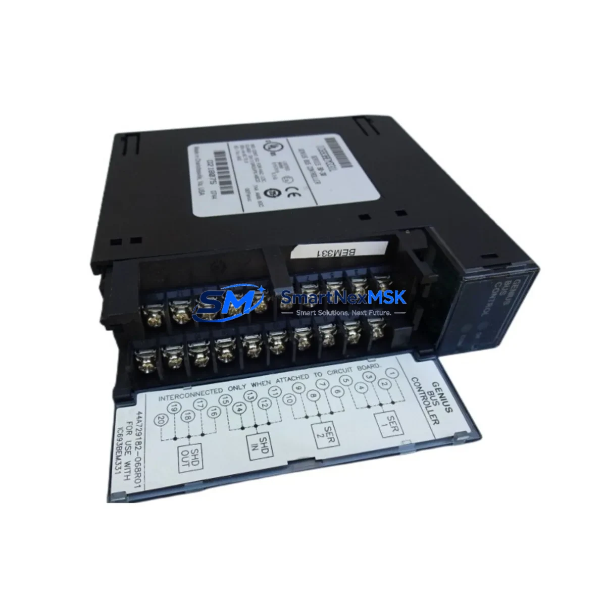
On the Genius bus side, map every device connected to the bus segment managed by the IC693BEM331. Genius I/O blocks — including remote discrete blocks and analog terminal assemblies — each carry a unique bus address (0–31). Record these addresses and confirm they match the hardware configuration stored in the Proficy Machine Edition project. If the site uses a GE Genius Hand-Held Monitor (IC660HHM501) for bus diagnostics, use it to capture a live bus scan before shutdown; this provides a reference for post-replacement verification.
Wiring adaptation is typically straightforward for a same-model replacement: the IC693BEM331 uses a standard Genius bus connector (two-wire shielded cable, Belden 9182 or equivalent). Confirm that the bus termination network — typically a 75-ohm resistor at each physical end of the Genius cable — is intact and correctly positioned. A missing or misplaced terminator is one of the most common causes of bus communication errors after a module swap.
For sites migrating from an older IC693BEM331 revision to a newer one, or planning a longer-term migration toward a PACSystems RX3i platform using the IC695ETM001 Ethernet module or IC695PBM300 PROFIBUS master, the IC693BEM331 replacement provides an opportunity to document the existing Genius I/O map in preparation for future I/O remapping. Engineers should also verify that the IC693CMM321 communications coprocessor (if installed) and any IC693BEM320 Genius Bus Controller modules on parallel bus segments are operating correctly, as a single bus fault can cascade across the rack.
Downtime Control During System Migration
Minimizing unplanned downtime during an IC693BEM331 replacement requires a structured hot-swap protocol. Begin by placing the Series 90-30 CPU in Stop/Fault-tolerant mode using Proficy Machine Edition or the Logicmaster 90 programmer, ensuring that all Genius bus outputs are held in their last-known state or driven to a safe de-energized condition as defined in the application program. Coordinate with the process control team to confirm that any interlocked systems — conveyors, drives, valve actuators — are in a safe hold state before removing power from the rack.
Back up the complete hardware configuration and ladder logic program to a local engineering workstation before touching any hardware. Store a copy of the IC693BEM331 bus controller configuration — including bus address, scan list, and fault reporting parameters — as a separate export file. This ensures that if the replacement module requires reconfiguration, the original parameters are immediately available without relying on memory or legacy paper documentation.
After installing the replacement IC693BEM331, power up the rack and observe the module’s status LEDs: the Bus Active LED should illuminate within seconds as the controller re-establishes communication with all Genius bus devices. Use the Genius Hand-Held Monitor or the PME online diagnostics view to confirm that all 32 (or fewer) bus devices are reporting correctly. Only after all devices are confirmed online should the CPU be returned to Run mode. Total replacement time for a prepared team is typically 15–45 minutes, keeping production interruption to a minimum.
Retrofit Support FAQ
Q: Is the IC693BEM331 a direct drop-in replacement for all Series 90-30 racks?
A: The IC693BEM331 is compatible with all standard Series 90-30 5-slot and 10-slot baseplates (IC693CHS391, IC693CHS397). It is not compatible with Series 90-70 or PACSystems RX3i racks. Confirm your chassis model before ordering.
Q: Do I need to reconfigure the bus controller after replacing the IC693BEM331?
A: If the replacement module is the same hardware revision, the bus controller configuration stored in the CPU’s hardware configuration file (via Proficy Machine Edition) is typically retained and re-applied automatically on power-up. If the revision differs, download the hardware configuration from PME to the CPU after installation to ensure correct bus address and scan list parameters are applied.
Q: What wiring changes are required when installing a replacement IC693BEM331?
A: No wiring changes are required for a same-model replacement. Reconnect the Genius bus cable (two-wire shielded, Belden 9182 or equivalent) to the module’s bus connector. Verify bus termination at both physical ends of the Genius cable. Do not alter the cable shield grounding arrangement.
Q: What does the 12-month warranty cover, and how are units tested before shipment?
A: Every IC693BEM331 shipped by SMARTNEXMSK undergoes functional testing including power-on self-test verification, backplane communication check, and Genius bus initialization confirmation. The 12-month warranty covers hardware defects and functional failures under normal operating conditions. Units are shipped with anti-static packaging and include a test report on request.
© 2026 SMARTNEXMSK. All rights reserved.
Original Source: https://smartnexmsk.com
Contact: sales@smartnexmsk.com | +86 18259474341


