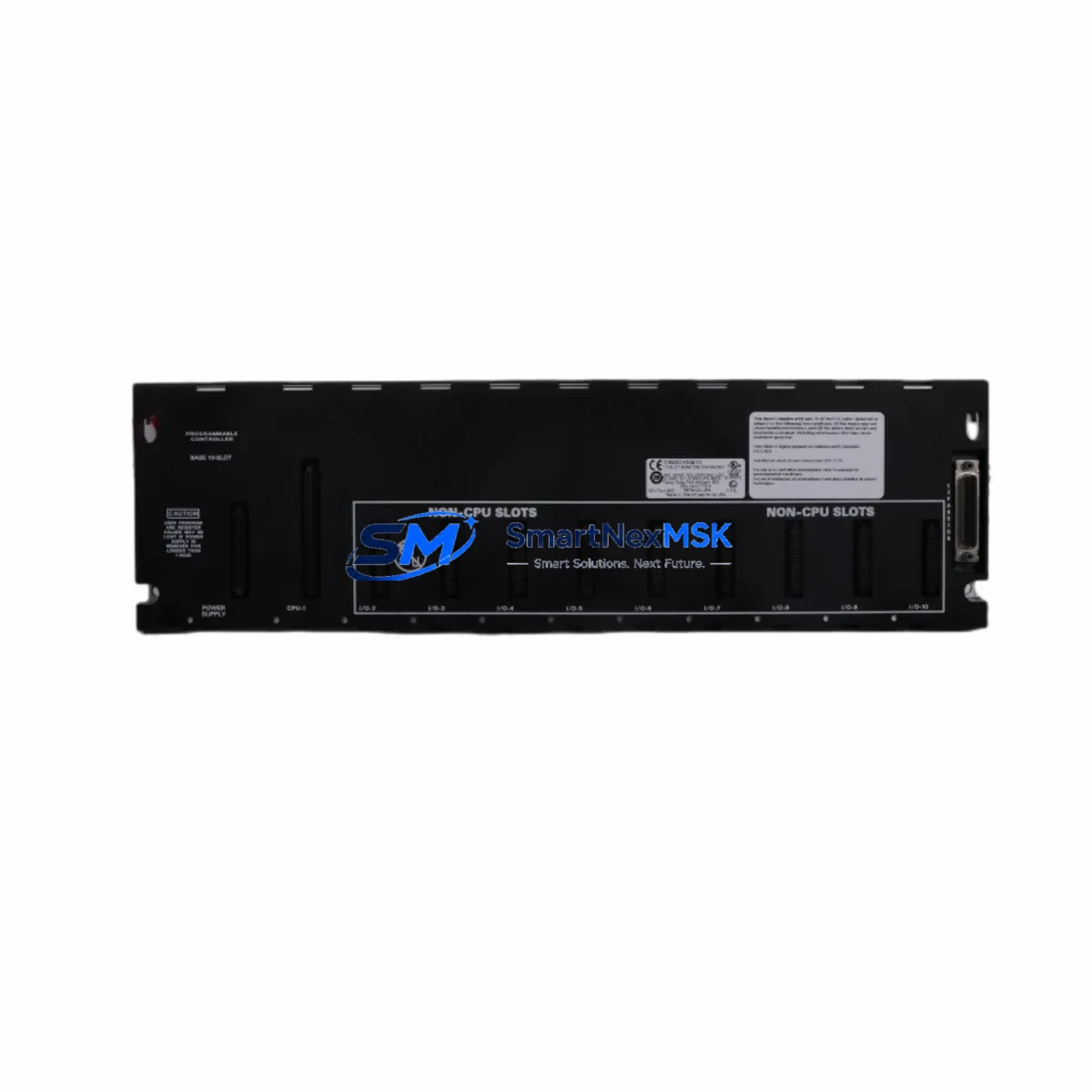
GE IC693CHS391 Retrofit-Ready 10-Slot Expansion Base for Series 90-30 Control Systems
The GE IC693CHS391 is a 10-slot expansion baseplate engineered for the GE Fanuc Series 90-30 programmable logic controller platform. As legacy Series 90-30 installations continue to operate across manufacturing, utilities, and process industries, the IC693CHS391 serves as the critical backbone for expanding I/O capacity, replacing cracked or corroded baseplates, and restoring full rack functionality without requiring a complete control system overhaul. Whether you are managing a planned retrofit or responding to an unplanned failure, this baseplate provides a verified drop-in replacement path that preserves your existing wiring infrastructure, module addressing, and ladder logic programs.
Industrial facilities running Series 90-30 CPUs such as the IC693CPU374 or IC693CPU364 frequently encounter baseplate degradation after 15–20 years of continuous operation. The IC693CHS391 restores full slot capacity, allowing engineers to reinstall existing analog input modules like the IC693ALG221, discrete output modules such as the IC693MDL940, and communications modules including the IC693CMM321 Ethernet interface — all without reprogramming or reconfiguring the control system from scratch.
Upgrade Compatibility Table
| Parameter | IC693CHS391 Details |
|---|---|
| Platform Compatibility | GE Fanuc Series 90-30 PLC |
| Slot Count | 10 I/O slots + 1 CPU/power slot |
| Backplane Interface | Series 90-30 parallel backplane bus |
| Power Supply Compatibility | IC693PWR321, IC693PWR322, IC693PWR330 |
| Installation Type | DIN rail or panel mount |
| Communication Compatibility | SNP, SNP-X, Ethernet (via CMM module) |
| Replacement Recommendation | Direct drop-in for IC693CHS391 (same revision) |
| Commissioning Notes | Verify slot addressing in Logicmaster 90 or Proficy ME before power-on |
| Warranty | 12 months from date of shipment |
| Origin | Tested, inspected, and shipped from verified stock |
Retrofit Planning for Existing Automation Systems
A successful IC693CHS391 baseplate retrofit begins well before the replacement unit arrives on-site. Engineers should document the current slot assignments for every installed module — including the CPU, power supply, and all I/O cards — and photograph the terminal wiring on each module before removal. This documentation becomes essential when reinstalling modules into the replacement baseplate and verifying that module addresses match the original configuration stored in the PLC program.
Power supply capacity is the first technical checkpoint. The IC693PWR321 (30W) and IC693PWR330 (40W) are the most common power supplies paired with the IC693CHS391. Before installing additional I/O modules during the upgrade, calculate the total backplane current draw to confirm the existing power supply can support the expanded load. If the current budget is tight, upgrading to the IC693PWR330 simultaneously with the baseplate replacement is a common and cost-effective decision.
Terminal wiring on modules such as the IC693MDL655 discrete input module and IC693ALG390 analog output module should be labeled and photographed before disconnection. Many Series 90-30 installations use removable terminal blocks, which simplifies the swap process — the terminal block can be transferred directly to the replacement module without rewiring individual conductors. Confirm that the terminal block revision is compatible with the replacement module before assuming a direct transfer.
For systems using the IC693CMM321 Ethernet communications module or the IC693PCM301 programmable coprocessor module, verify that the backplane slot position is preserved in the replacement rack. Some CPU firmware versions are sensitive to the physical slot location of communications modules, and moving a CMM module to a different slot may require updating the hardware configuration in Proficy Machine Edition before the program will execute correctly.
If the existing system uses a IC693MDL752 relay output module or similar high-current output card, inspect the backplane connector on the replacement baseplate for any signs of arcing or contact wear before installation. Relay output modules place higher mechanical and electrical stress on backplane connectors than solid-state I/O modules, and a worn connector can cause intermittent faults that are difficult to diagnose after the system is returned to service.
For facilities planning a phased migration from Series 90-30 to a newer platform such as the PACSystems RX3i, the IC693CHS391 can serve as an interim solution that maintains production continuity while the new control system is configured, tested, and validated offline. The RX3i platform supports Series 90-30 I/O modules through a compatibility carrier, allowing a gradual transition that avoids a full production shutdown.
Downtime Control During System Migration
Minimizing unplanned downtime during a baseplate replacement requires a structured pre-outage preparation process. Before scheduling the maintenance window, upload the current PLC program from the IC693CPU374 or equivalent CPU to a laptop running Proficy Machine Edition or Logicmaster 90-30 software. Store a verified backup of the program, hardware configuration, and any motion or PID parameters in at least two separate locations. Confirm that the programming cable — typically a IC690ACC901 serial programming cable or a USB-to-serial adapter with the correct driver — is functional and available on-site before the outage begins.
During the replacement window, work systematically from left to right across the baseplate, removing one module at a time and placing it in an anti-static bag labeled with its slot number. Transfer the modules to the replacement IC693CHS391 in the same order, verifying that each module seats fully into the backplane connector before moving to the next slot. After all modules are installed, reconnect the power supply and apply power without enabling outputs. Use the PLC programming software to verify that all modules are recognized in the hardware configuration and that no fault codes are present before enabling field outputs and returning the system to automatic mode.
For critical processes where even a brief interruption is unacceptable, consider pre-staging the replacement baseplate with all modules installed and tested in a bench environment before the scheduled outage. This approach reduces the on-site replacement time to the duration required for disconnecting and reconnecting field wiring, which can often be completed within a single shift.
Retrofit Support FAQ
Q: Is the IC693CHS391 a direct replacement for my existing Series 90-30 expansion baseplate?
A: Yes. The IC693CHS391 is a direct drop-in replacement for the same model number in the Series 90-30 platform. All existing I/O modules, power supplies, and CPU cards install into the replacement baseplate without modification. Verify the revision level of your existing baseplate if you are using early-revision modules, as some first-generation Series 90-30 hardware has minor connector differences.
Q: Do I need to reprogram the PLC after replacing the baseplate?
A: No reprogramming is required if all modules are reinstalled in their original slot positions. The PLC program and hardware configuration are stored in the CPU module, not the baseplate. However, it is strongly recommended to upload and verify a current backup of the program before beginning the replacement, and to perform a hardware configuration download after the replacement to confirm that all modules are recognized correctly.
Q: What commissioning steps are required after installation?
A: After installing all modules into the replacement IC693CHS391, apply power and connect a programming device to the CPU. Verify that all modules appear in the hardware configuration without fault indicators. Check I/O forcing status to confirm no forces are active from the previous maintenance session. Enable outputs in a controlled sequence and verify field device responses before returning the system to automatic operation. Document the commissioning results for your maintenance records.
Q: What warranty coverage is provided with the IC693CHS391?
A: All IC693CHS391 units supplied by SMARTNEXMSK are covered by a 12-month warranty from the date of shipment. Each unit undergoes functional testing and visual inspection prior to dispatch. Warranty coverage includes replacement or repair of any unit that fails under normal operating conditions within the warranty period. Contact our technical support team at sales@smartnexmsk.com for warranty claims or pre-shipment technical verification requests.
© 2026 SMARTNEXMSK. All rights reserved.
Original Source: https://smartnexmsk.com
Contact: sales@smartnexmsk.com | +86 18259474341


