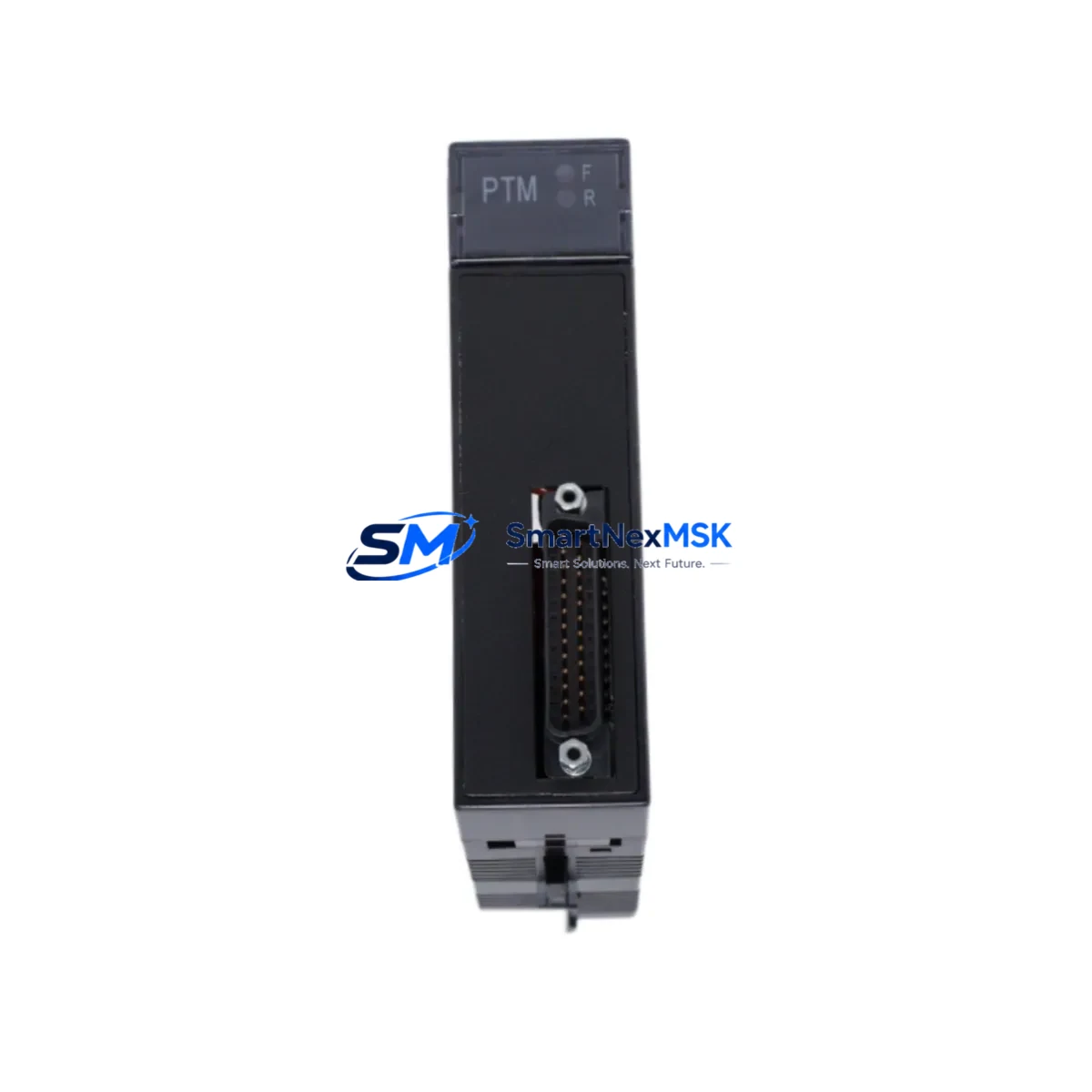
GE IC693PTM101 Maintenance-Ready Spare for Series 90-30 Automation
The GE IC693PTM101 is an original Power Transducer Module designed for the GE Series 90-30 PLC platform — one of the most widely deployed programmable logic controller families in industrial automation. For maintenance engineers managing aging control systems, the IC693PTM101 represents a critical spare that directly impacts uptime, power monitoring accuracy, and system stability. Whether you are executing a planned shutdown, responding to an unscheduled fault, or building a proactive spare parts inventory, having a verified replacement IC693PTM101 on hand is a fundamental risk-reduction strategy for any facility running Series 90-30 hardware.
The IC693PTM101 interfaces with the Series 90-30 backplane to provide real-time power transducer data to the CPU, enabling accurate monitoring of voltage, current, and power factor across critical electrical circuits. Failure or degradation of this module can result in loss of power quality visibility, nuisance alarms, or — in worst-case scenarios — undetected electrical anomalies that escalate into equipment damage or unplanned downtime. Sourcing a tested, original-specification replacement is therefore not optional for facilities with zero-tolerance downtime requirements.
Every IC693PTM101 unit supplied by SMARTNEXMSK is sourced from verified industrial channels, functionally tested prior to shipment, and backed by a 12-month warranty. Units are packaged to IPC/ESD standards to prevent transit damage and are ready for immediate installation upon receipt.
Spare Maintenance Table
| Parameter | Specification / Detail |
|---|---|
| Part Number | IC693PTM101 |
| Manufacturer | GE (General Electric Automation) |
| Series | Series 90-30 |
| Module Type | Power Transducer Module |
| Backplane Compatibility | GE Series 90-30 5-slot, 10-slot, and expansion racks |
| Measured Parameters | Voltage, Current, Power Factor, Real/Reactive Power |
| Communication Interface | Series 90-30 backplane bus |
| Operating Temperature | 0°C to 60°C (32°F to 140°F) |
| Mounting | Direct backplane slot insertion — no external wiring adapter required |
| Origin | United States |
| Condition | Original, functionally tested |
| Warranty | 12 months from date of shipment |
| Packaging | ESD-safe anti-static bag, foam-padded carton |
| Lead Time | In-stock units ship within 1–3 business days |
| Application Environment | Industrial control panels, power monitoring systems, utility substations, manufacturing automation |
| Maintenance Recommendation | Inspect every 12–24 months; replace immediately upon fault code or power data anomaly |
Maintenance Planning for Continuous Operation
When a maintenance or procurement engineer identifies the IC693PTM101 as a replacement requirement, the scope of inspection should extend beyond the module itself. The Series 90-30 platform is a tightly integrated system, and a power transducer fault often signals stress or degradation in adjacent components that share the same electrical circuit or backplane slot neighborhood.
Begin with the IC693PWR321 or IC693PWR330 power supply module — the primary source feeding the rack. A failing or under-spec power supply is frequently the root cause of transducer anomalies and should be load-tested before the new IC693PTM101 is commissioned. Inspect the IC693CPU364 or IC693CPU374 CPU module for any active fault codes logged in the diagnostic buffer that may correlate with the power transducer failure event.
Check all IC693MDL series analog and digital I/O modules in the same rack for signs of voltage irregularity — particularly the IC693ALG221 analog input module and IC693MDL940 relay output module, which are sensitive to power rail fluctuations. Inspect the IC693CMM321 communications module if the system uses Ethernet or serial data exchange, as power anomalies can corrupt communication buffers and cause intermittent network faults.
Terminal blocks and field wiring connected to the transducer’s measurement inputs should be inspected for loose connections, corrosion, or insulation breakdown — particularly in high-humidity or high-vibration environments. Verify that IC693ACC300 series expansion cables and backplane connectors are seated correctly and show no signs of arcing or heat damage. If the control cabinet includes signal isolators between the transducer outputs and downstream SCADA or HMI inputs, confirm that those isolators — often DIN-rail mounted units from the same electrical loop — are within calibration and operating range.
For facilities running legacy Series 90-30 systems beyond their original design life, this replacement event is also an appropriate time to audit the overall spare parts inventory. Stocking a second IC693PTM101, along with a backup power supply and at least one CPU module, provides a meaningful buffer against extended lead times for obsolete or end-of-life GE hardware.
Site Replacement Workflow
Step 1 — Pre-replacement verification: Confirm the fault is isolated to the IC693PTM101 by reviewing the CPU diagnostic log and checking for fault codes specific to the power transducer slot. Document the current module configuration using the GE Proficy Machine Edition programming software before removal.
Step 2 — Safe de-energization: Follow your site’s lockout/tagout (LOTO) procedure. De-energize the rack and allow capacitors to discharge before removing the module. The IC693PTM101 is a hot-swap-capable module on some firmware revisions — verify your CPU firmware version before attempting live replacement.
Step 3 — Module removal and inspection: Remove the faulty IC693PTM101 and inspect the backplane connector for bent pins, carbon deposits, or moisture ingress. Clean the slot with compressed air if necessary before inserting the replacement unit.
Step 4 — Replacement installation: Insert the new IC693PTM101 firmly into the designated backplane slot. Re-energize the rack and confirm the module status LED indicates normal operation. The CPU should automatically recognize the module and resume data acquisition without requiring a program download in most Series 90-30 configurations.
Step 5 — Functional verification: Use Proficy Machine Edition or the Series 90-30 hand-held programmer to verify that power transducer data is being correctly reported to the CPU. Cross-check readings against a calibrated clamp meter or power analyzer to confirm measurement accuracy before returning the system to production.
Step 6 — Documentation and spare replenishment: Log the replacement in your CMMS, update the equipment history record, and initiate a purchase order for a replacement spare to restore your buffer stock. Downtime events caused by single-point-of-failure spare shortages are entirely preventable with a disciplined replenishment cycle.
Spare Parts Support FAQ
Q1: Is the IC693PTM101 still in production, and how long can I expect supply availability?
The GE Series 90-30 platform has reached end-of-active-production, but the IC693PTM101 remains available through authorized industrial spare parts distributors and MRO channels. SMARTNEXMSK maintains stock of verified original units and monitors supply chain availability to support long-term maintenance programs. We recommend customers with ongoing Series 90-30 installations consider purchasing 1–2 additional units as strategic buffer stock given the platform’s obsolescence trajectory.
Q2: How is each IC693PTM101 tested before shipment?
Every unit undergoes functional bench testing that verifies backplane communication, measurement channel integrity, and LED status indication prior to packaging. Units that fail any test parameter are quarantined and not shipped. A test report is available upon request for customers with quality documentation requirements. All units are shipped in ESD-safe packaging with a 12-month warranty covering manufacturing defects and functional failures under normal operating conditions.
Q3: Can the IC693PTM101 replace older GE Series 90-30 power transducer variants without reprogramming?
In most cases, yes. The IC693PTM101 is designed as a direct slot-compatible replacement within the Series 90-30 rack architecture. However, customers should verify their CPU firmware version and Proficy Machine Edition project configuration to confirm that the module type reference in the hardware configuration matches. If the existing project was configured for an earlier revision, a minor hardware configuration update and program download may be required. Our technical team can assist with compatibility verification prior to purchase.
Q4: What is covered under the 12-month warranty, and what is the return process?
The 12-month warranty covers functional failures and manufacturing defects under normal industrial operating conditions. It does not cover damage resulting from incorrect installation, overvoltage events, physical impact, or unauthorized modification. To initiate a warranty claim, contact sales@smartnexmsk.com with your order number, a description of the fault symptom, and any available diagnostic data. We will issue a return authorization and arrange for inspection and replacement or refund within the agreed service timeline.
© 2026 SMARTNEXMSK. All rights reserved.
Original Source: https://smartnexmsk.com
Contact: sales@smartnexmsk.com | +86 18259474341


