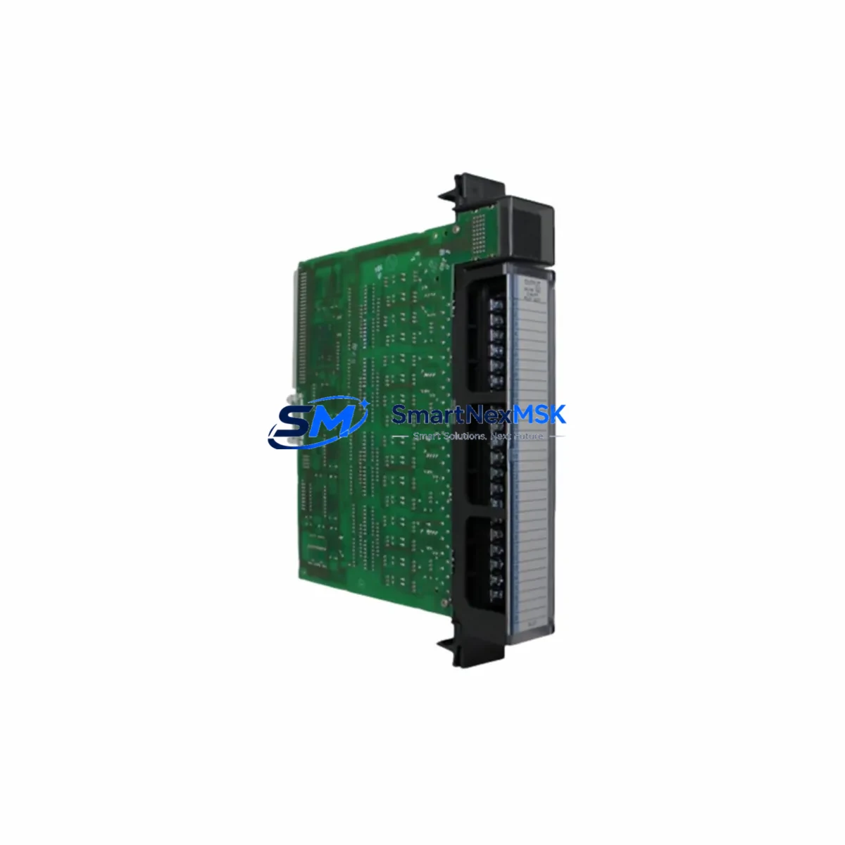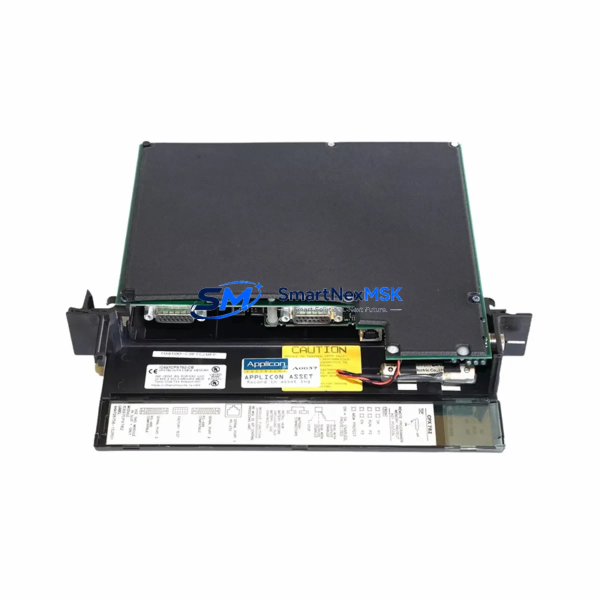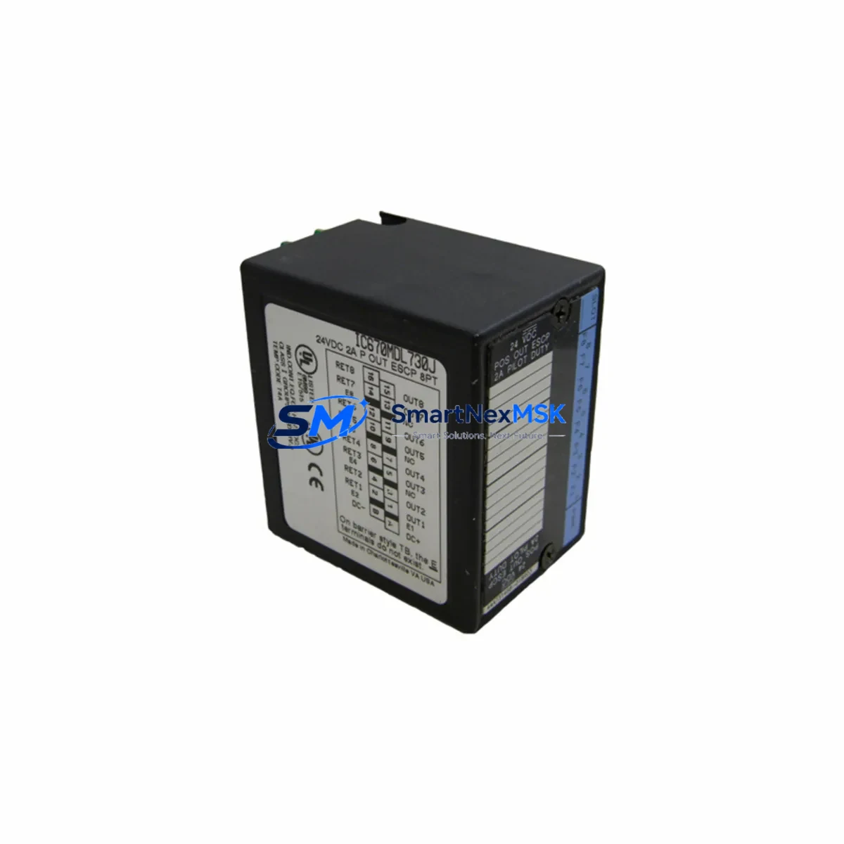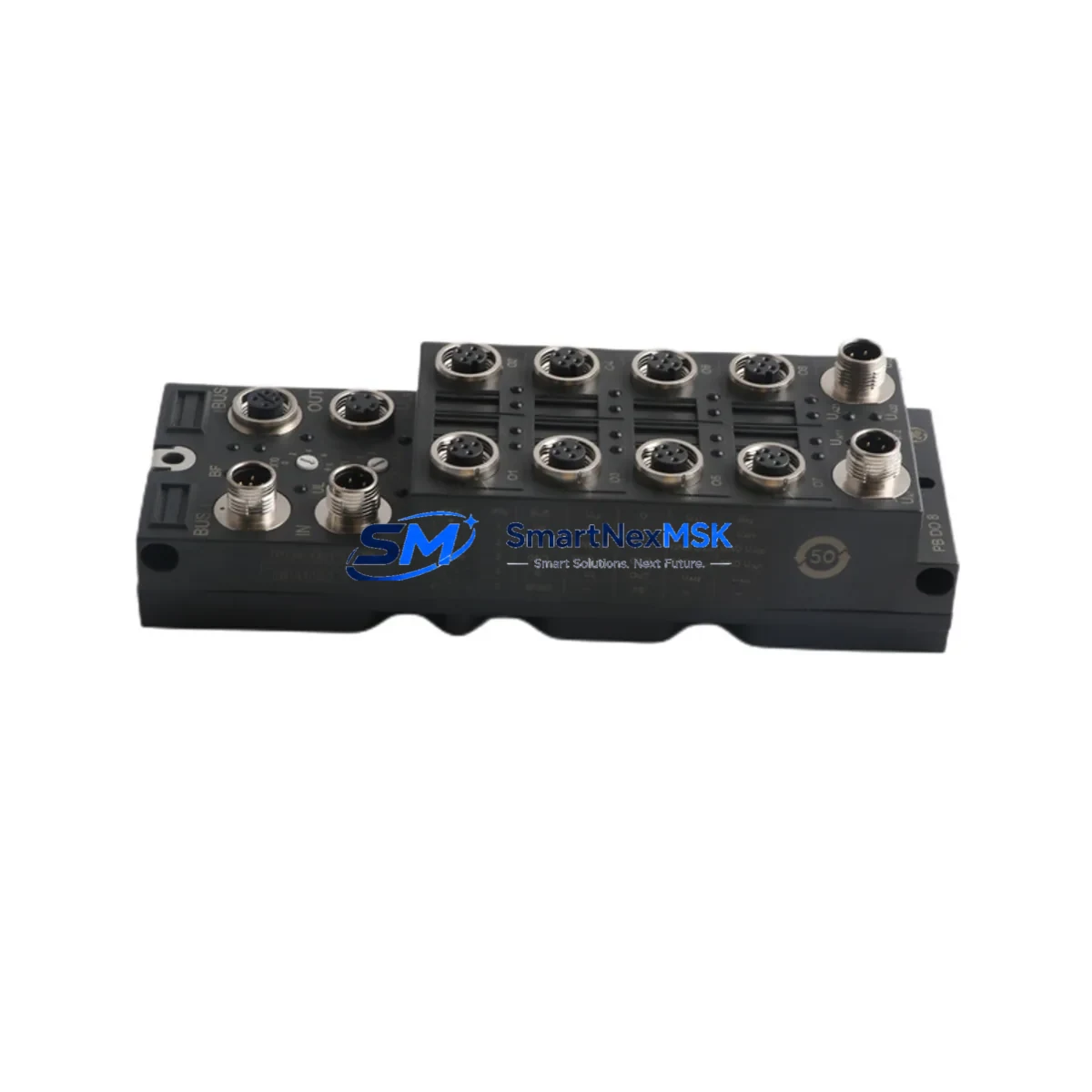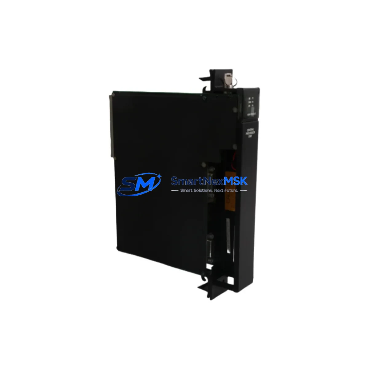
GE IC697CPX782 Retrofit-Ready CPU for Series 90-70 Control Systems
The GE IC697CPX782 is a high-performance CPU module engineered for the GE Series 90-70 programmable logic controller platform — one of the most widely deployed industrial control architectures in process manufacturing, power generation, and heavy industry. As original equipment manufacturers phase out support for legacy Series 90-70 hardware, the IC697CPX782 has become the preferred retrofit solution for facilities seeking to extend operational life, reduce unplanned downtime, and preserve existing ladder logic investments without committing to a full control system overhaul.
Whether you are replacing a failed IC697CPU772 or IC697CPU781, upgrading from an earlier-generation processor, or consolidating a multi-rack Series 90-70 installation onto a single high-capacity CPU, the IC697CPX782 delivers the processing headroom and memory capacity required for modern supervisory demands. Its compatibility with the standard IC697CHS750 and IC697CHS782 VME backplane racks means physical installation follows the same slot-assignment conventions your maintenance team already knows.
Upgrade Compatibility Table
| Parameter | IC697CPX782 (This Unit) | Typical Legacy CPU (IC697CPU772) |
|---|---|---|
| Backplane Interface | VME 9-slot / 5-slot rack compatible | VME 9-slot / 5-slot rack compatible |
| User Memory | Up to 512 KB program / 512 KB data | Up to 128 KB program / 128 KB data |
| Communication Ports | RS-232 (Port 1 & 2), SNP/SNPX, Ethernet via IC697CMM742 | RS-232 (Port 1), SNP only |
| I/O Scan Compatibility | Full Series 90-70 I/O bus | Full Series 90-70 I/O bus |
| Programming Software | Proficy Machine Edition (ME) / Logicmaster 90-70 | Logicmaster 90-70 |
| Replacement Recommendation | Direct drop-in for IC697CPU772, CPU781, CPU788 | — |
| Installation Requirement | Slot 1 of master rack; verify rack power budget | Slot 1 of master rack |
| Commissioning Note | Re-download program via ME or LM90; verify I/O map | — |
| Warranty | 12 Months | OEM warranty expired |
Retrofit Planning for Existing Automation Systems
A successful IC697CPX782 retrofit begins well before the module arrives on site. The first step is a power budget audit of the host rack. The IC697CHS750 nine-slot rack and IC697CHS782 five-slot rack each carry a defined backplane power capacity; adding a higher-performance CPU alongside existing IC697MDL340 discrete input modules, IC697MDL341 output modules, and IC697ALG320 analog input modules can push the rack close to its supply limit. Confirm that the installed IC697PWR711 or IC697PWR724 power supply can sustain the combined load before powering up.
Terminal wiring on the I/O modules does not change during a CPU swap — field wiring connected to your existing terminal blocks remains undisturbed. However, if the retrofit is part of a broader communication upgrade, this is the ideal moment to install or verify the IC697CMM742 Ethernet communications module, which enables TCP/IP-based SRTP programming and HMI connectivity. Facilities still relying on serial SNP links to a Cimplicity or third-party HMI should audit their RS-232 cable pinouts and baud-rate settings, as the IC697CPX782 supports both SNP and SNPX protocols but requires explicit port configuration in Proficy Machine Edition.
Module addressing in the Series 90-70 is rack-and-slot based. After seating the IC697CPX782 in Slot 1, verify that all remote I/O drops — typically connected via IC697BEM711 Bus Expansion Modules — retain their configured rack addresses. Any address conflict introduced during the swap will prevent the CPU from completing its I/O scan and will generate a hardware fault on startup. Document the existing rack/slot map before removal and cross-check it against the new CPU’s configuration table in Proficy ME.
For sites running Logicmaster 90-70 programs, the ladder logic can be uploaded from the outgoing CPU before removal (if it is still partially functional) or restored from a backup .prg file. The IC697CPX782 accepts Logicmaster-format programs loaded via Proficy ME’s conversion utility, preserving rung structure, variable names, and I/O references. After download, perform a full I/O force test on non-critical outputs before returning the system to automatic mode.
Downtime Control During System Migration
Minimizing production interruption during a Series 90-70 CPU replacement requires a structured pre-outage checklist. At least 48 hours before the scheduled maintenance window, upload and verify the current program from the existing CPU, export the hardware configuration, and photograph all terminal wiring and module positions. If the plant operates a redundant control path — for example, a secondary IC697CPU788 in a hot-standby arrangement — confirm that the standby unit can assume full control before initiating the swap.
During the outage, place the system in Stop/Fault mode, remove the legacy CPU from Slot 1, and seat the IC697CPX782 firmly until the VME connector is fully engaged. Restore the hardware configuration first, then download the application program. The IC697CPX782’s faster scan cycle means that time-critical rungs — particularly those governing conveyor sequencing, valve interlocks, or PID loops — should be reviewed for any scan-time dependencies before the first live run.
After program download, execute a controlled warm-start and monitor the CPU’s diagnostic LEDs: a steady green RUN indicator with no FAULT or BAT LEDs active confirms a clean initialization. Verify HMI tag connectivity — whether through a Cimplicity project or a third-party SCADA reading via the IC697CMM742 Ethernet module — before releasing the system to operators. Total planned outage for a straightforward CPU swap typically ranges from two to four hours when pre-outage preparation is complete.
Retrofit Support FAQ
Q1: Is the IC697CPX782 a direct replacement for the IC697CPU772 and IC697CPU781?
Yes. The IC697CPX782 occupies the same Slot 1 position in any standard Series 90-70 VME rack and uses the same backplane bus protocol. No hardware modifications to the rack, I/O modules, or field wiring are required. The primary post-swap task is re-downloading the application program using Proficy Machine Edition or Logicmaster 90-70.
Q2: What commissioning steps are required after installation?
After seating the module, restore the hardware configuration file, download the application program, verify the I/O address map against your rack/slot documentation, and perform a controlled warm-start. Check all communication links — SNP serial, SNPX, or Ethernet via IC697CMM742 — and confirm HMI tag updates before returning to automatic operation. A full I/O force test on non-critical outputs is recommended before live production.
Q3: How do I verify wiring and terminal compatibility before the swap?
Field wiring connects to I/O modules (such as IC697MDL340 or IC697ALG320), not directly to the CPU, so terminal wiring is unaffected by the CPU replacement. Verify the rack power budget against the IC697PWR711 or IC697PWR724 supply rating, and confirm that Bus Expansion Module (IC697BEM711) rack addresses are correctly documented before removal.
Q4: What does the 12-month warranty cover, and how is the unit tested before shipment?
Every IC697CPX782 unit supplied by SMARTNEXMSK undergoes functional power-on testing, diagnostic LED verification, and communication port checks prior to shipment. The 12-month warranty covers hardware defects and functional failures under normal operating conditions. Units are shipped in anti-static packaging with full documentation. For warranty claims or technical support, contact [email protected].
© 2026 SMARTNEXMSK. All rights reserved.
Original Source: https://smartnexmsk.com
Contact: [email protected] | +86 18259474341