GE IC697PWR710 Retrofit-Ready Power Supply for Series 90-70 Control Systems
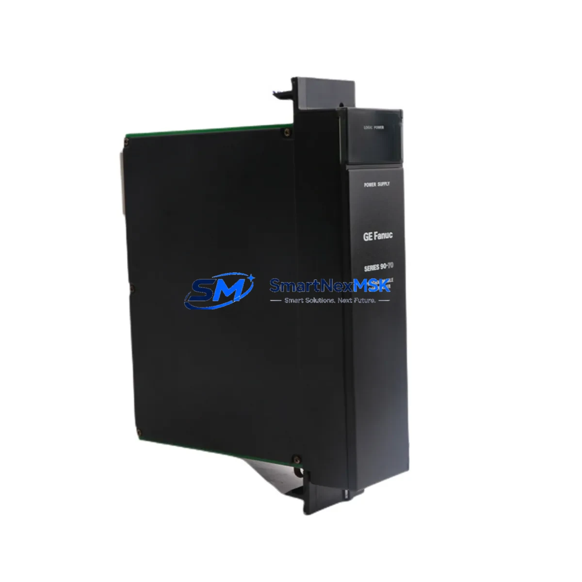
The GE IC697PWR710 is a 120/240 VAC input power supply module designed for the GE Series 90-70 programmable logic controller platform. As legacy Series 90-70 systems approach end-of-life and original spare parts become increasingly scarce, the IC697PWR710 remains one of the most critical components for sustaining continuous production in process control, discrete manufacturing, and utility automation environments. SMARTNEXMSK maintains verified stock of the IC697PWR710 with full functional testing, 12-month warranty coverage, and rapid dispatch from our Xiamen facility to support urgent retrofit and emergency replacement requirements worldwide.
Whether you are executing a planned control system modernization, responding to an unplanned module failure, or building a strategic spare parts inventory for aging GE Series 90-70 infrastructure, the IC697PWR710 provides a direct, rack-compatible replacement that eliminates the need for immediate full-system migration. Its compatibility with the IC697CHS750 and IC697CHS782 baseplate racks, combined with standard backplane connector alignment, means that experienced automation engineers can complete a hot-swap replacement with minimal disruption to the surrounding I/O architecture.
Upgrade Compatibility Table
| Parameter | IC697PWR710 Specification | Retrofit Notes |
|---|---|---|
| Input Voltage | 120/240 VAC, 47–63 Hz | Verify site supply voltage before installation; no jumper change required between 120 V and 240 V ranges on this model |
| Output Power | +5 VDC @ 13 A, +/-15 VDC @ 0.5 A | Confirm total backplane load does not exceed rated output; calculate I/O module draw across IC697CHS750 or IC697CHS782 rack |
| Rack Compatibility | IC697CHS750 (9-slot), IC697CHS782 (5-slot) | Slot 0 installation; backplane connector is keyed — no adapter required |
| CPU Compatibility | IC697CPU731, IC697CPU771, IC697CPU782 | No firmware change required; CPU recognizes PSU on power-up self-test |
| Communication Modules | IC697CMM711, IC697CMM742 (Ethernet/Serial) | Communication links remain active during PSU swap if redundant power is available |
| Terminal Wiring | Screw-terminal AC input block | Re-use existing field wiring; torque to 0.5 N·m; verify ground continuity before energizing |
| Replacement for | IC697PWR710A, IC697PWR710B (suffix variants) | Functionally interchangeable across all suffix revisions; confirm label before ordering if suffix-specific firmware is required |
| Commissioning Test | Full load burn-in, output voltage verification | Each unit ships with test report; verify +5 VDC rail with calibrated meter at backplane test points |
| Warranty | 12 Months | Covers manufacturing defects and functional failure under normal operating conditions; DOA replacement within 7 days |
Retrofit Planning for Existing Automation Systems
A successful IC697PWR710 retrofit begins well before the module arrives on site. Engineers responsible for Series 90-70 system maintenance should start by auditing the full rack configuration: document every module installed in the IC697CHS750 or IC697CHS782 chassis, record the current draw of each analog and digital I/O card, and confirm that the replacement IC697PWR710 can sustain the aggregate backplane load. In multi-rack systems where an IC697BEM711 bus expansion module connects remote I/O racks, the power budget calculation must account for all downstream modules drawing from the primary rack supply.
Terminal block wiring is the next critical checkpoint. The IC697PWR710 uses a removable screw-terminal AC input connector. Before disconnecting the failed unit, photograph the existing wiring layout and label each conductor. This step is especially important in installations where the control cabinet also houses an IC697MDL340 discrete output module or an IC697ALG440 analog input module sharing the same cabinet ground bus. Maintaining ground integrity throughout the swap protects both the replacement PSU and the connected field instruments.
For systems running Logicmaster 90 or Proficy Machine Edition ladder programs stored on the IC697CPU771 or IC697CPU782 CPU module, the program memory is retained in battery-backed RAM during the power supply replacement. Confirm that the CPU battery — typically a lithium cell mounted on the IC697ACC701 memory backup module — is within its service life before initiating the swap. A depleted backup battery combined with an unplanned power interruption is the most common cause of program loss during PSU maintenance. If the site uses an IC697CMM742 Ethernet communications module for SCADA connectivity, notify the control room operator to expect a brief communication dropout during the power cycle.
In retrofit projects that involve migrating from an older IC697PWR711 or IC697PWR724 power supply to the IC697PWR710, verify that the replacement module’s output current rating is sufficient for the expanded I/O count that often accompanies a system upgrade. Projects that add IC697MDL653 high-density digital input modules or IC697ALG320 analog output modules to an existing rack must recalculate the total +5 VDC load before finalizing the PSU selection. SMARTNEXMSK’s technical team can assist with load calculations and compatibility verification prior to order confirmation.
Downtime Control During System Migration
Minimizing unplanned downtime is the primary concern for any production facility undertaking a Series 90-70 power supply replacement. The IC697PWR710 is designed for tool-free module extraction from the IC697CHS750 rack, which reduces the physical swap time to under five minutes for a trained technician. However, the total migration window must also account for system restart, I/O verification, and communication link re-establishment — steps that typically add 15 to 30 minutes depending on the complexity of the installed IC697CMM711 or IC697CMM742 network configuration.
To protect the original control program during the replacement, always verify that the IC697CPU771 or IC697CPU782 CPU is in STOP mode before removing the power supply. This prevents any mid-cycle output state changes that could affect connected actuators or drives. If the system controls a continuous process where even a brief output interruption is unacceptable, coordinate with the process team to place the loop in manual mode at the DCS or HMI level before initiating the PLC power cycle. For facilities using a GE Cimplicity or iFIX HMI, update the alarm suppression list to prevent nuisance alarms during the planned outage window.
After the IC697PWR710 is seated and the AC input is restored, allow the Series 90-70 system to complete its full power-on self-test sequence before switching the CPU back to RUN mode. Monitor the +5 VDC backplane voltage at the rack test points and confirm that all I/O module status LEDs return to their normal operating state. Document the replacement date, module serial number, and post-installation voltage readings in the site maintenance log. This record supports warranty claims and provides a baseline for future preventive maintenance scheduling.
Retrofit Support FAQ
Q1: Is the IC697PWR710 a direct drop-in replacement for the IC697PWR710A and IC697PWR710B suffix variants?
Yes. The IC697PWR710, IC697PWR710A, and IC697PWR710B are functionally interchangeable across all GE Series 90-70 rack configurations. The suffix designations reflect minor hardware revisions that do not affect electrical performance, backplane connector pinout, or CPU compatibility. No firmware update or configuration change is required when substituting between suffix variants.
Q2: What wiring checks are required before installing the replacement IC697PWR710?
Before installation, verify that the AC input voltage at the terminal block matches the module’s rated input range (120/240 VAC), confirm that the protective earth conductor is securely terminated and continuity-tested, and inspect the existing wiring for insulation damage or loose terminations. Re-torque all screw terminals to 0.5 N·m after seating the module. If the cabinet also contains an IC697MDL340 output module or other inductive loads, confirm that surge suppression devices are in place on the AC supply line.
Q3: Will the CPU program be lost during the power supply swap?
Not under normal conditions. The IC697CPU771 and IC697CPU782 CPU modules retain their ladder logic programs in battery-backed RAM. Provided the CPU backup battery is serviceable, the program will survive the power interruption. Before beginning the swap, verify battery status via the Logicmaster 90 or Proficy Machine Edition programmer connected through the IC697CMM711 serial port or the IC697CMM742 Ethernet port. Replace the battery if the low-battery indicator is active.
Q4: What does the 12-month warranty cover, and how does SMARTNEXMSK handle DOA units?
The 12-month warranty covers all manufacturing defects and functional failures under normal operating conditions from the date of shipment. Each IC697PWR710 unit undergoes full load burn-in testing and output voltage verification before dispatch, and ships with a test report. In the event of a dead-on-arrival (DOA) unit, SMARTNEXMSK will arrange priority replacement shipment within 7 business days of receiving the returned module and fault confirmation. Contact sales@smartnexmsk.com with your order number and a description of the observed fault to initiate a warranty claim.
© 2026 SMARTNEXMSK. All rights reserved.
Original Source: https://smartnexmsk.com
Contact: sales@smartnexmsk.com | +86 18259474341


